Multi-phase boost converter with phase self-detection and detecting circuit thereof

a phase self-detection and converter technology, applied in the direction of electric variable regulation, process and machine control, instruments, etc., can solve the problems of unnecessary power consumption, waste of quiescent current of circuitry, and inability to save corresponding switching loss, so as to reduce excess power consumption

Active Publication Date: 2016-11-15
ANPEC ELECTRONICS CORPORATION
View PDF4 Cites 0 Cited by
  • Summary
  • Abstract
  • Description
  • Claims
  • Application Information

AI Technical Summary

Benefits of technology

[0012]In summary, the provided multi-phase boost converter with phase self-detection and the detecting circuit can determine whether to control the switching transistors of each phase according to detecting whether an inductor at the corresponding phase exists. Accordingly, the PWM controller of the multi-phase boost converter does not need to perform related control about the switching transistors of the phase without coupling an inductor, so as to achieve reduced excess power consumption.

Problems solved by technology

However, the phase without inductor still switches, therefore, the related operation quiescent current of circuitry is then wasted and of course the corresponding switching loss is not saved.
Thus, the PWM controller 15 still controls the first switch LG1˜LGn and the second switch UG1˜UGn, so as to result in unnecessary power consumption.

Method used


Image

  • Multi-phase boost converter with phase self-detection and detecting circuit thereof
  • Multi-phase boost converter with phase self-detection and detecting circuit thereof
  • Multi-phase boost converter with phase self-detection and detecting circuit thereof

Examples


Embodiment Construction

[0021]Reference will now be made in detail to the exemplary embodiments of the present disclosure, examples of which are illustrated in the accompanying drawings. Wherever possible, the same reference numbers are used in the drawings and the description to refer to the same or like parts.

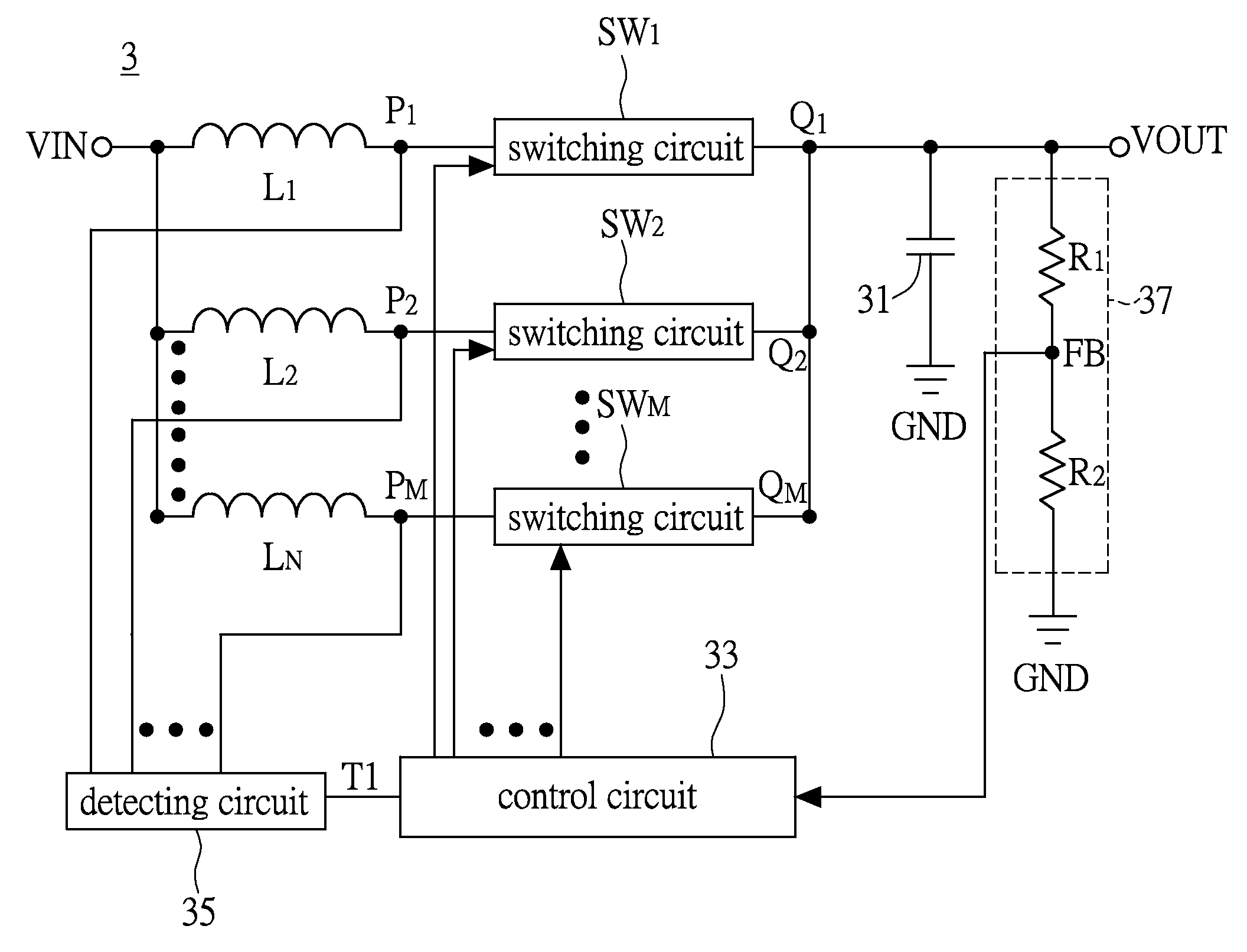
[0022]Firstly, please refer to FIG. 3 showing a block diagram of a multi-phase boost converter with phase self-detection according to an embodiment of the instant disclosure. The multi-phase boost converter 3 comprises M switching circuits SW1˜SWM, a capacitor 31, a control circuit 33 and a detecting circuit 35. The switching circuits SW1˜SWM, the capacitor 31, a control circuit 33 and the detecting circuit 35 can be implemented completely by a hardware circuit, or implemented by hardware cooperating with firmware or software. In short, the instant disclosure does not limit the implementation manner of the multi-phase boost converter 3. Additionally, the switching circuits SW1˜SWM, the capacitor 31,...


PUM


Abstract

A multi-phase boost converter with phase self-detection and a detecting circuit thereof are provided. The multi-phase boost converter comprises M switching circuits, a capacitor, a control circuit and a detecting circuit. Each switching circuit has an input end and an output end. N inductors are coupled in parallel between the input ends and an input voltage. The output ends are coupled to an output voltage. The control circuit controls the conduction status of the switching circuits according to a feedback voltage corresponding to the output voltage. The detecting circuit coupled between the input ends and the control circuit detects the conduction status between the input voltage and each of the input ends, for outputting a first control signal. The control circuit controlled by the first control signal selectively controls at least one of the switching circuits. N is a positive integer less than or equal to M.

Description

BACKGROUND OF THE INVENTION[0001]1. Field of the Invention[0002]The instant disclosure relates to a multi-phase boost converter with phase self-detection and a detecting circuit thereof; in particular, to a multi-phase boost converter with phase self-detection and a detecting circuit thereof which can determine whether to control the switching transistors of each phase by detecting if an inductor of each phase of the multi-phase boost converter exists, so as to decrease unnecessary power consumption.[0003]2. Description of Related Art[0004]An electronic device usually contains various different elements, and the operation voltage of each element may also be different. Thus, in the electronic device, a DC to DC voltage converter is needed to achieve the regulation of the voltage level (rising the voltage or decreasing the voltage), such that each element can receive a stable voltage level. Depending on different power requirements, a variety of DC / DC voltage converters are proposed. ...

Claims


Application Information

Patent Timeline
Patent Type & Authority Patents(United States)
IPC IPC(8): H02M3/158H02M3/156
CPCH02M3/158H02M3/156H02M3/1584Y02B70/10H02M1/0048
Inventor CHEN, YU-YUCHEN, CHIH-YUAN
Owner ANPEC ELECTRONICS CORPORATION
Why Eureka
Try Eureka