Image forming apparatus, and method of controlling image forming apparatus

a technology of image forming apparatus and forming apparatus, which is applied in the direction of electrographic process apparatus, instruments, optics, etc., can solve the problems of excessive power consumption, delay in printing operation, and power control apparatus cannot determine whether the packet is being printed, so as to reduce excess power consumption

Active Publication Date: 2015-09-29
CANON KK
View PDF11 Cites 0 Cited by
  • Summary
  • Abstract
  • Description
  • Claims
  • Application Information

AI Technical Summary

Benefits of technology

[0010]Aspects of the present invention are generally directed to enabling recovery from a sleep state in an optimum power state without unnecessary waste to reduce excess power consumption.

Problems solved by technology

In this case, a power control apparatus cannot determine whether the packet received via the network is a job packet that requires printing operation or any other packet such as an inquiry about the apparatus.
This may cause a delay in printing operation after the recovery from the sleep state.
Furthermore, the supply of power to every device at the time of recovery from the sleep state may lead to excess power consumption if the packet received via the network is a mere inquiry of the status of the apparatus.

Method used


Image

  • Image forming apparatus, and method of controlling image forming apparatus
  • Image forming apparatus, and method of controlling image forming apparatus
  • Image forming apparatus, and method of controlling image forming apparatus

Examples


Embodiment Construction

[0034]Exemplary embodiments will be described below with reference to the drawings.

[0035]The following describes a first exemplary embodiment.

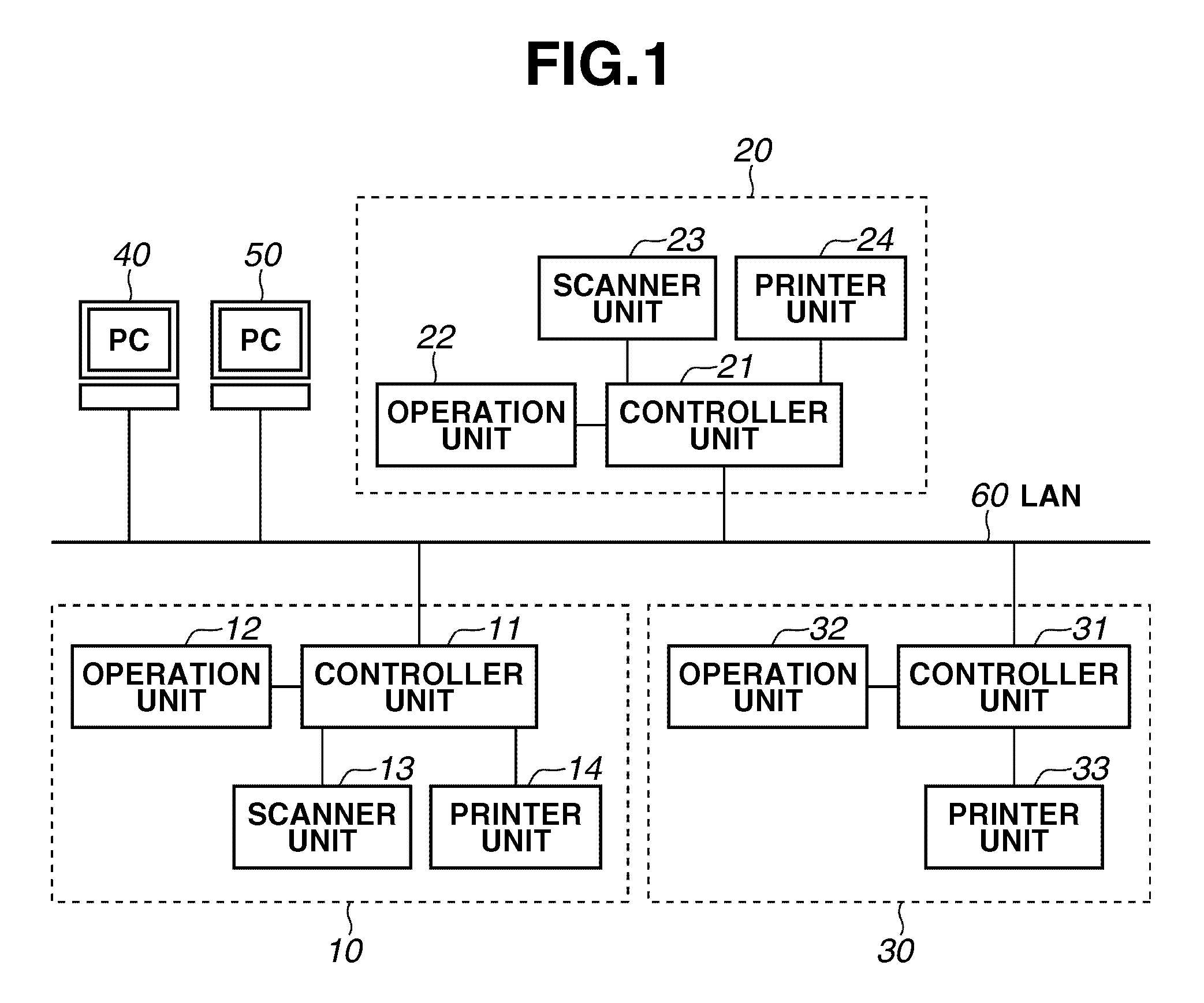
[0036]FIG. 1 is a block diagram illustrating an example of the configuration of a network system to which an image forming apparatus according to the exemplary embodiment is applicable. In the example illustrated in FIG. 1, host computers 40 and 50 and image forming apparatuses 10, 20, and 30 are connected to a local area network (LAN) 60, but the number of apparatuses connected to the system according to the exemplary embodiment is not limited to that in the example illustrated in FIG. 1. Further, although the present exemplary embodiment adopts the LAN to connect apparatuses, this embodiment is not seen to be limiting to the LAN. For example, an arbitrary network such as a wide area network (WAN) (public line) is also adoptable.

[0037]The host computers (hereinafter “PCs”) 40 and 50 have a function of a general personal computer. The PCs 40 a...


PUM


Abstract

In a first power state of an image forming apparatus in which a first power supply unit supplies power to a network I / F but does not supply power to a central processing unit (CPU), if a received packet is a first type packet, a power supply control unit shifts the image forming apparatus to a second power state in which the first power supply unit supplies power to the CPU but the second power supply unit does not supply power to the image forming unit. If the received packet is a second type packet, the power supply control unit shifts the image forming apparatus to a third power state in which the first power supply unit supplies power to the CPU and the second power supply unit supplies power to the image forming unit.

Description

BACKGROUND[0001]1. Field[0002]Aspects of the present invention generally relate to a control executed at the time when an image forming apparatus being in a sleep state receives a packet via a network to recover the image forming apparatus.[0003]2. Description of the Related Art[0004]Conventionally, an image forming apparatus that performs network communication has a function to automatically shift to a sleep state to reduce power consumption when the image forming apparatus has not been used for a predetermined period or longer. While the image forming apparatus is in the sleep state, another apparatus operates the image forming apparatus via a network to recover the image forming apparatus from the sleep state.[0005]A method for the recovery from the sleep state has been discussed in which an image forming apparatus receives an input signal from a network and recovers from the sleep state if a pattern of the received input signal matches an input signal pattern that is registered ...

Claims


Application Information

Patent Timeline
Patent Type & Authority Patents(United States)
IPC IPC(8): G03G15/00
CPCG03G15/80G03G15/5004
Inventor YAMAMIZU, HIROSHI
Owner CANON KK
Why Eureka
Try Eureka