Atherectomy catheters and occlusion crossing devices

a technology of atherectomy and crossing device, which is applied in the field of atherectomy catheters, can solve the problems of occlusion of arteries, inaccurate images obtained from atherectomy devices, and catastrophic consequences, and achieve the effect of clear imaging region and safe bend

Active Publication Date: 2016-11-22
AVINGER
View PDF416 Cites 37 Cited by
  • Summary
  • Abstract
  • Description
  • Claims
  • Application Information

AI Technical Summary

Benefits of technology

[0013]Also described herein are catheters including high-powered flushing ‘jets’ that can be used to pack material (cut material) into the hollow nosecone, as well as to clear the imaging region. These jet flushing ports may also be configured to create a venturi effect that can be used to suck material into the nosecone and / or away from the imaging / cutting head and / or the distal end region of the elongate body.
[0014]Also described herein are techniques and structures for managing the optical fiber at the proximal end (e.g., the handle) of the catheter. In devices in which the optical fiber and drive shaft rotate and may move laterally (proximally / distally), an optical fiber management chamber at the proximal end of the device before the coupling region for coupling the optical fiber to the imaging system. The optical fiber management chamber may be cylindrical. The optical fiber management chamber typically includes a hollow space in which the fiber, as it moves laterally relative to the proximal coupling region, may safely bend. The optical fiber management chamber rotates with the optical fiber, so there is no relative rotational motion between the optical fiber management chamber and the optical fiber.
[0029]This and other embodiments can include one or more of the following features. The plurality of jet channels can include two channels extending along an inner circumference of the bushing. The jet channels can be positioned to create a venturi effect at the distal end of the cutting and imaging assembly.
[0035]The first balloon may span the hinge region. For example, as mentioned above, the first balloon may be attached to a region that is proximal to the hinge region (on the elongate body) and distal to the hinge region (on the nosecone). The first balloon may also be oriented so that it expands (e.g., pushing) just one side of the catheter device (the side opposite the hinge region and / or the cutting window) to both drive the cutter against the wall of a vessel and to help displace the nosecone and expose the cutting edge of the cutter.
[0041]In general the second balloon is proximal to the first balloon and is an occluding balloon which may help occlude blood flow through the vessel when inflated. The second balloon may extend circumferentially around elongate body. For example, the second balloon may be configured to block the flow of blood, which may prevent interference in imaging and / or cutting. The first (C-shaped) balloon and the second balloon may be spaced apart to optimize the occlusive ability of the second (occlusion) balloon and the displacement of the distal nosecone and apposition of the cutter to the vessel by the first (apposition) balloon. For example, the second balloon may be less than 100 cm (e.g., less than 90 cm, less than 85 cm, less than 80 cm, less than 75 cm, less than 70 cm, etc.) from the first balloon and / or between 10 cm and 100 cm (e.g., between 10 cm and 80 cm, between 10 cm and 75 cm, between 20 cm and 80 cm, between 20 cm and 75 cm, between 30 cm and 75 cm, between 40 cm and 75 cm, between 50 cm and 75 cm, etc.).

Problems solved by technology

PAD and CAD are silent, dangerous diseases that can have catastrophic consequences when left untreated.
Over time, this substance hardens and thickens, which can cause an occlusion in the artery, completely or partially restricting flow through the artery.
Images obtained from an atherectomy device, however, can be inaccurate due to the placement of the imaging sensor at a location that is far from the cutter.
As a result, it can be difficult to visualize the tissue being cut.
Moreover, minimally-invasive techniques can be inefficient, as often many devices are required to perform a single procedure.

Method used


Image

  • Atherectomy catheters and occlusion crossing devices
  • Atherectomy catheters and occlusion crossing devices
  • Atherectomy catheters and occlusion crossing devices

Examples


Embodiment Construction

[0099]Described herein are atherectomy catheters and occlusion-crossing catheters.

Atherectomy Catheters

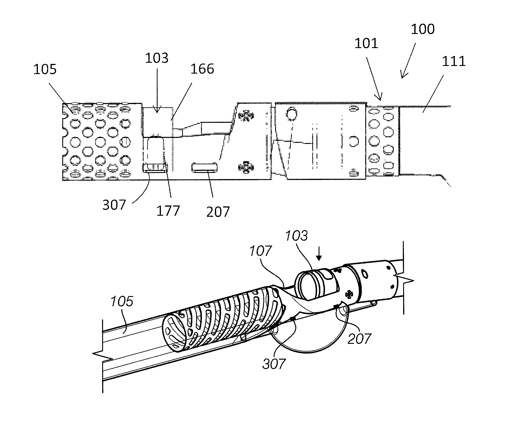
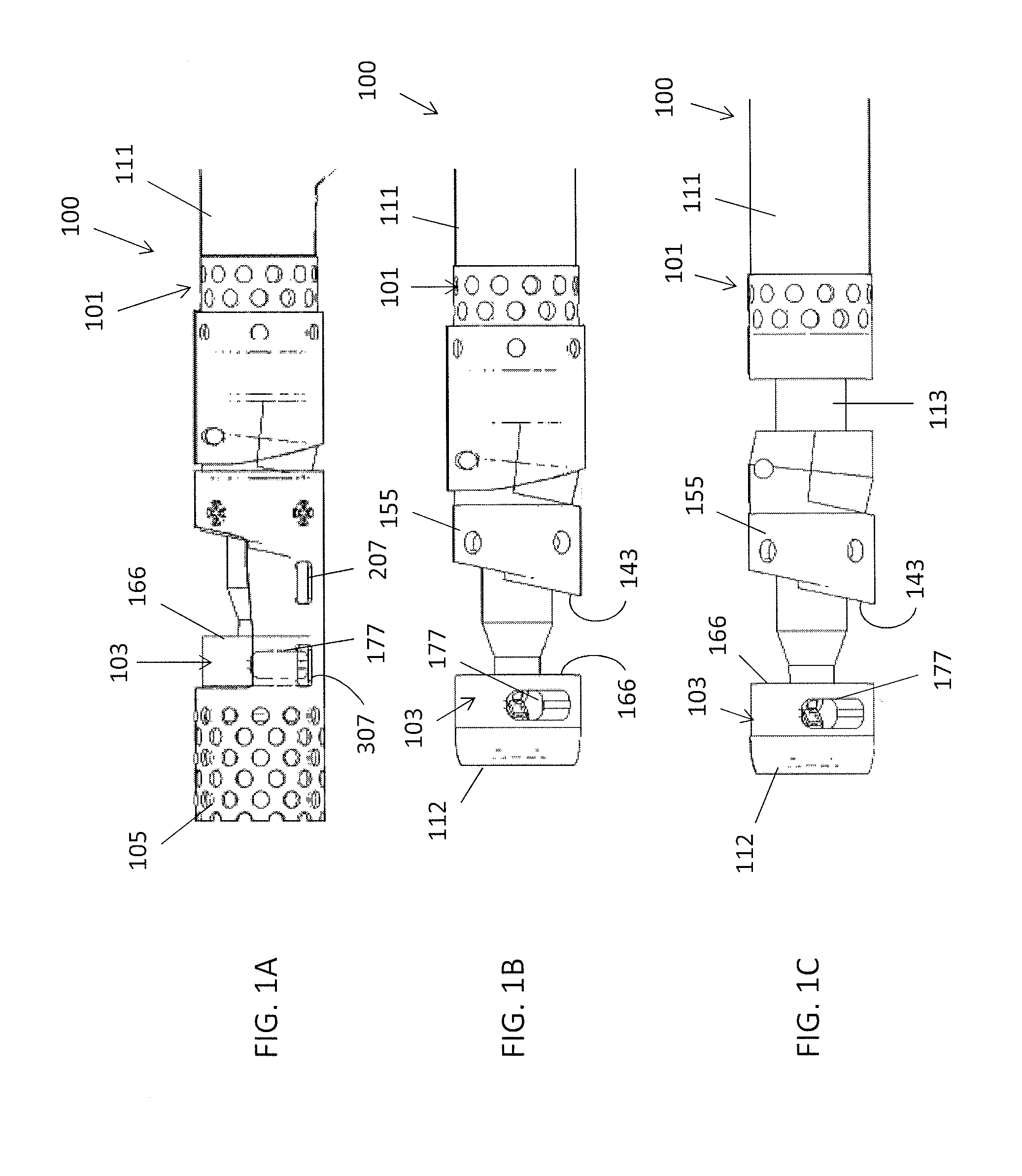
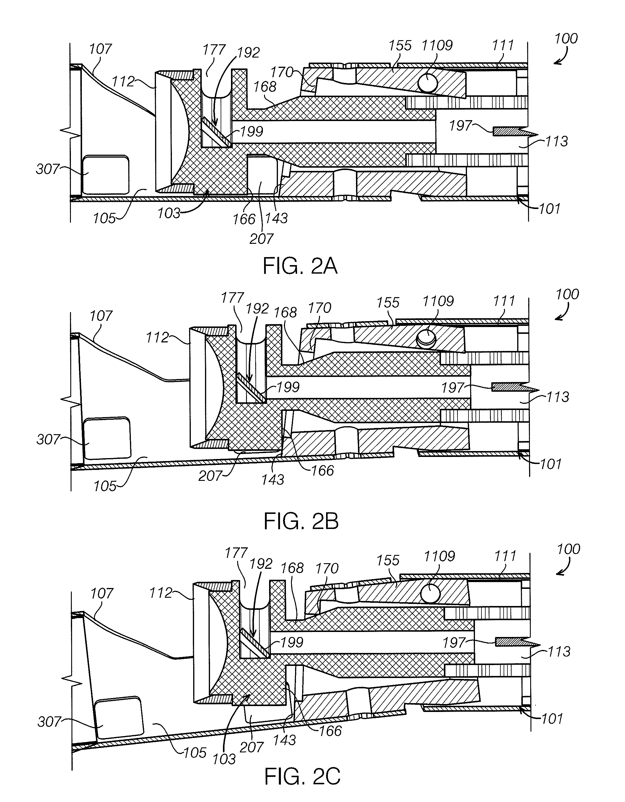
[0100]The atherectomy catheters described herein can include a catheter shaft with a drive chassis on the end. The drive chassis includes a stout torque coil (“imaging torqueing coil” / drive shaft) for rotating an imaging element, a cutter, and an imaging optical fiber in the center of the torque coil. Both the imaging elements and the cutter can be part of a head that rotates with the driveshaft. The head can rotate in a single direction (e.g., clockwise). The head can further slide distally / proximally by pushing or pulling the torque coil / drive shaft. As a result of the movement of the driveshaft, a nosecone configured to hold tissue can be displaced. In some embodiments, the nosecone can open and close using an off-axis hinge. In other embodiments, a cam member and cam slot can be used to open and close the nosecone.

[0101]FIGS. 1A-3 show an example of an atherectomy catheter 100 ...


PUM


Abstract

Atherectomy catheter devices having a C-shaped balloon opposite a cutting window out of which a rotating cutter may extend and a proximal annular balloon. The C-shaped first balloon may be used to drive the cutter against a vessel and to deploy the cutter by assisting in deflecting a nosecone (distal tip) to expose the distal-facing cutting edge of the cutter. The proximal annular balloon may be used to occlude blood flow. The device may pulled, pushed or rotated in a vessel with the balloons inflated or deflated.

Description

CROSS REFERENCE TO RELATED APPLICATIONS[0001]This application is a continuation-in-part of: U.S. patent application Ser. No. 15 / 072,272, filed Mar. 16, 2016, titled “ATHERECTOMY CATHETERS DEVICES HAVING MULTI-CHANNEL BUSHINGS”, which claimed priority as a continuation-in-part of International Patent Application No. PCT / US2015 / 014613, filed Feb. 5, 2015, titled “ATHERECTOMY CATHETERS AND OCCLUSION CROSSING DEVICES”, Publication No. WO 2015-120146, which claimed priority to U.S. Provisional Patent Application No. 61 / 936,837, titled “ATHERECTOMY CATHETERS AND OCCLUSION CROSSING DEVICES,” filed Feb. 6, 2014. Each of these applications is herein incorporated by reference in its entirety.[0002]This application is also a continuation in part of International Patent Application No. PCT / US2015 / 014613, filed Feb. 5, 2015, titled “ATHERECTOMY CATHETERS AND OCCLUSION CROSSING DEVICES,” Publication No. WO 2015-120146, which claims priority to U.S. Provisional Patent Application No. 61 / 936,837, t...

Claims


Application Information

Patent Timeline
Patent Type & Authority Patents(United States)
IPC IPC(8): A61B17/22A61D1/02A61B17/3207A61B17/00
CPCA61B17/320725A61B2017/00557A61B5/0066A61B5/0084A61B5/02007A61B5/6853A61B17/320758A61B17/320783A61B2017/00738A61B2017/22067A61B2017/22071A61B2017/320791A61M25/0043A61M25/0068A61M25/0074A61M25/0082A61B2090/3735A61B17/12031A61B17/1204A61B17/12109A61B17/12136A61M25/1002A61M25/1011A61B90/37
Inventor PATEL, HIMANSHU N.SIMPSON, JOHN B.LAM, WENDY NGO
Owner AVINGER
Why Eureka
Try Eureka