Atherectomy catheters devices having multi-channel bushings

a catheter and multi-channel technology, applied in the field of atherectomy catheters, can solve the problems of occlusion of arteries, inaccurate images obtained from atherectomy devices, and catastrophic consequences, and achieve the effect of clear imaging region and safe bend

Active Publication Date: 2017-03-14
AVINGER
View PDF437 Cites 31 Cited by
  • Summary
  • Abstract
  • Description
  • Claims
  • Application Information

AI Technical Summary

Benefits of technology

[0023]Also described herein are catheters including high-powered flushing ‘jets’ that can be used to pack material (cut material) into the hollow nosecone, as well as to clear the imaging region. These jet flushing ports may also be configured to create a venturi effect that can be used to suck material into the nosecone and / or away from the imaging / cutting head and / or the distal end region of the elongate body.
[0024]Also described herein are techniques and structures for managing the optical fiber at the proximal end (e.g., the handle) of the catheter. In devices in which the optical fiber and drive shaft rotate and may move laterally (proximally / distally), an optical fiber management chamber at the proximal end of the device before the coupling region for coupling the optical fiber to the imaging system. The optical fiber management chamber may be cylindrical. The optical fiber management chamber typically includes a hollow space in which the fiber, as it moves laterally relative to the proximal coupling region, may safely bend. The optical fiber management chamber rotates with the optical fiber, so there is no relative rotational motion between the optical fiber management chamber and the optical fiber.
[0039]This and other embodiments can include one or more of the following features. The plurality of jet channels can include two channels extending along an inner circumference of the bushing. The jet channels can be positioned to create a venturi effect at the distal end of the cutting and imaging assembly.

Problems solved by technology

PAD and CAD are silent, dangerous diseases that can have catastrophic consequences when left untreated.
Over time, this substance hardens and thickens, which can cause an occlusion in the artery, completely or partially restricting flow through the artery.
Images obtained from an atherectomy device, however, can be inaccurate due to the placement of the imaging sensor at a location that is far from the cutter.
As a result, it can be difficult to visualize the tissue being cut.
Moreover, minimally-invasive techniques can be inefficient, as often many devices are required to perform a single procedure.
Although atherectomy devices having a distal cutting edge that can be covered and exposed by moving a distal tip have been described, the forces necessary to displace the distal tip reliably and repeatedly have proven undesirably large and difficult to operate reliably.

Method used


Image

  • Atherectomy catheters devices having multi-channel bushings
  • Atherectomy catheters devices having multi-channel bushings
  • Atherectomy catheters devices having multi-channel bushings

Examples


Embodiment Construction

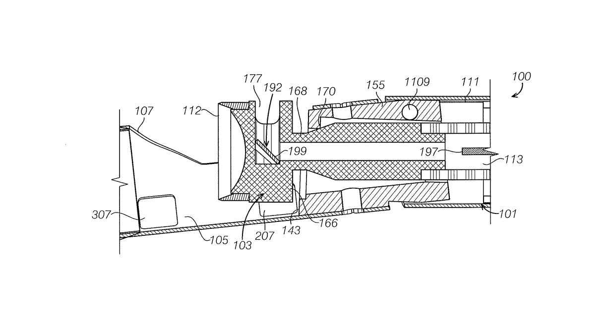
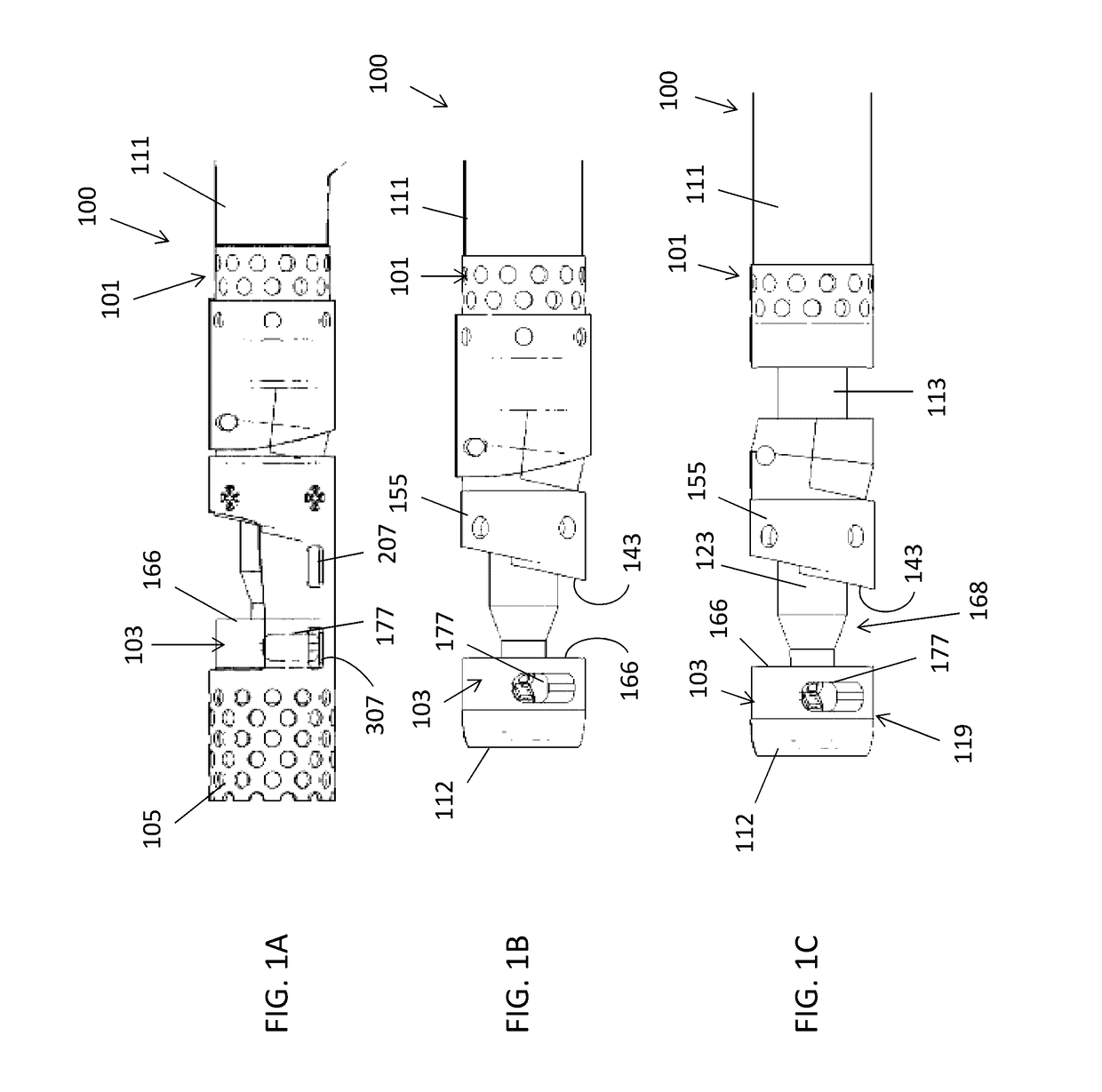
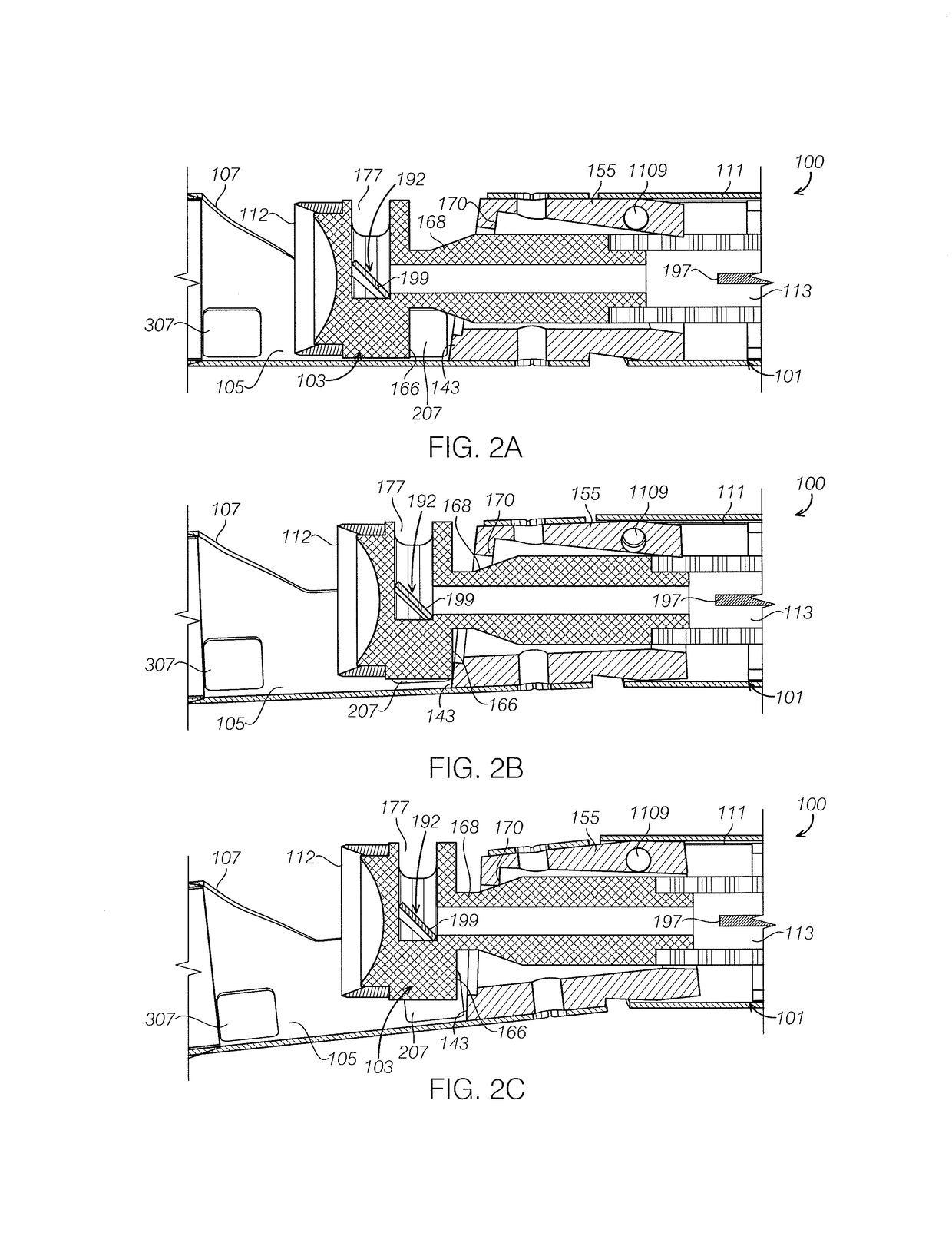
[0069]Described herein are atherectomy catheters and occlusion-crossing catheters. In particular, described herein are catheters having distal tip that may be deflected (e.g., to expose a rotating cutter) in a mechanically advantageous manner by use of a multi-channel bushing having a radially offset hinge point or points and a pair of flange points. The operation of the rotating cutter head within the multi-channel bushing may be actuated by the drive shaft by pushing and pulling, and may translate axial motion of the drive shaft into radial bending / movement of the tip to create a deflection requiring relatively little force and / or lateral deflection.

Atherectomy Catheters

[0070]The atherectomy catheters described herein can include a catheter shaft with a drive chassis on the end. The drive chassis includes a stout torque coil (“imaging torqueing coil” / drive shaft) for rotating an imaging element, a cutter, and an imaging optical fiber in the center of the torque coil. Both the imag...


PUM


Abstract

Atherectomy catheters and methods of using them are described herein. In particular, described herein are optical coherence tomography (OCT) catheters that may include a distal tip that can be deflected away from the long axis of the device using a multi-channel bushing. The bushing may include at a hinge point that is offset (e.g., located on a side of the elongate body near the distal end of the elongate body) and a rotatable cutter near an imaging assembly that can be driven against the wall with a high mechanical advantage.

Description

CROSS REFERENCE TO RELATED APPLICATIONS[0001]This application claims priority as a continuation-in-part of International Patent Application No. PCT / US2015 / 014613, titled “ATHERECTOMY CATHETERS AND OCCLUSION CROSSING DEVICES”, filed Feb. 5, 2015, which claimed priority to U.S. Provisional Patent Application No. 61 / 936,837, titled “ATHERECTOMY CATHETERS AND OCCLUSION CROSSING DEVICES,” filed Feb. 6, 2014, each of which is herein incorporated by reference in its entirety.INCORPORATION BY REFERENCE[0002]All publications and patent applications mentioned in this specification are herein incorporated by reference in their entirety to the same extent as if each individual publication or patent application was specifically and individually indicated to be incorporated by reference.FIELD[0003]Described herein are atherectomy catheters and methods of using them. In particular, described herein are atherectomy catheters that include a bushing configured to be hinged off-axis and include two ov...

Claims


Application Information

Patent Timeline
Patent Type & Authority Patents(United States)
IPC IPC(8): A61B17/22A61M25/00A61B5/00A61B17/3207A61D1/02
CPCA61B17/320783A61B5/0066A61B5/0084A61B17/320758A61M25/0043A61M25/0068A61M25/0074A61M25/0082A61B2017/320791A61B2090/3735
Inventor SIMPSON, JOHN B.PATEL, HIMANSHU N.FERNANDEZ, ANTHONY J.NEWHAUSER, RICHARD R.
Owner AVINGER
Why Eureka
Try Eureka