Atherectomy catheters and occlusion crossing devices

a technology of atherectomy and crossing device, which is applied in the field of atherectomy catheters, can solve the problems of occlusion of artery, low surgical efficiency, and inconvenient atherectomy, and achieve the effect of safe bend and clear imaging region

Active Publication Date: 2022-03-29
AVINGER
View PDF633 Cites 1 Cited by
  • Summary
  • Abstract
  • Description
  • Claims
  • Application Information

AI Technical Summary

Benefits of technology

[0020]Also described herein are catheters including high-powered flushing ‘jets’ that can be used to pack material (cut material) into the hollow nosecone, as well as to clear the imaging region. These jet flushing ports may also be configured to create a venturi effect that can be used to suck material into the nosecone and / or away from the imaging / cutting head and / or the distal end region of the elongate body.
[0021]Also described herein are techniques and structures for managing the optical fiber at the proximal end (e.g., the handle) of the catheter. In devices in which the optical fiber and drive shaft rotate and may move laterally (proximally / distally), an optical fiber management chamber at the proximal end of the device before the coupling region for coupling the optical fiber to the imaging system. The optical fiber management chamber may be cylindrical. The optical fiber management chamber typically includes a hollow space in which the fiber, as it moves laterally relative to the proximal coupling region, may safely bend. The optical fiber management chamber rotates with the optical fiber, so there is no relative rotational motion between the optical fiber management chamber and the optical fiber.
[0036]This and other embodiments can include one or more of the following features. The plurality of jet channels can include two channels extending along an inner circumference of the bushing. The jet channels can be positioned to create a venturi effect at the distal end of the cutting and imaging assembly.
[0042]The first balloon may span the hinge region. For example, as mentioned above, the first balloon may be attached to a region that is proximal to the hinge region (on the elongate body) and distal to the hinge region (on the nosecone). The first balloon may also be oriented so that it expands (e.g., pushing) just one side of the catheter device (the side opposite the hinge region and / or the cutting window) to both drive the cutter against the wall of a vessel and to help displace the nosecone and expose the cutting edge of the cutter.
[0048]In general the second balloon is proximal to the first balloon and is an occluding balloon which may help occlude blood flow through the vessel when inflated. The second balloon may extend circumferentially around elongate body. For example, the second balloon may be configured to block the flow of blood, which may prevent interference in imaging and / or cutting. The first (C-shaped) balloon and the second balloon may be spaced apart to optimize the occlusive ability of the second (occlusion) balloon and the displacement of the distal nosecone and apposition of the cutter to the vessel by the first (apposition) balloon. For example, the second balloon may be less than 100 cm (e.g., less than 90 cm, less than 85 cm, less than 80 cm, less than 75 cm, less than 70 cm, etc.) from the first balloon and / or between 10 cm and 100 cm (e.g., between 10 cm and 80 cm, between 10 cm and 75 cm, between 20 cm and 80 cm, between 20 cm and 75 cm, between 30 cm and 75 cm, between 40 cm and 75 cm, between 50 cm and 75 cm, etc.).

Problems solved by technology

PAD and CAD are silent, dangerous diseases that can have catastrophic consequences when left untreated.
Over time, this substance hardens and thickens, which can cause an occlusion in the artery, completely or partially restricting flow through the artery.
Despite its advantages, atherectomy is not commonly performed due to the cost, complexity and limited applicability of available atherectomy devices.
Many designs are unable to treat the wide range of disease states present in long complex lesions; luminal gain is often limited by the requirement of the physician to introduce multiple devices with increased crossing profiles; tissue collection is either unpredictable or considered unnecessary based on assumptions regarding small particle size and volumes; and optimal debulking is either not possible due to a lack of intravascular visualization or requires very long procedure times. Based on these limitations, current devices are likely to perform poorly in the coronary vasculature where safety and efficacy in de novo lesions, ostials, and bifurcations continue to pose great challenges.
When the plaque is not aspirated through the catheter to an external reservoir, the reliability of these devices to produce clinically insignificant embolization has been challenged.
In addition, options for post-procedural analysis of any removed disease are extremely limited or impossible using this methodology.
These large distal tip assemblies can limit the capability of the system to access small lesions and may cause additional trauma to the vessel.
Images obtained from an atherectomy device, however, can be inaccurate due to the placement of the imaging sensor at a location that is far from the cutter.
As a result, it can be difficult to visualize the tissue being cut.
Moreover, minimally-invasive techniques can be inefficient, as often many devices are required to perform a single procedure.
Moreover, currently available atherectomy devices also do not include, and are poorly adapted for use with, real time image guidance.
Further, several design challenges are presented by a single use, disposable, and single-direction imaging catheter, such as an atherectomy catheter.
For example, obtaining a clear image can be difficult, as nonuniform rotational distortion (“NURD”) can occur in the image as a result of the cutter vibrating or stalling as it encounters different types of tissue.
Further, a motor can be required to drive the imaging assembly at the appropriate revolution rates for imaging, thereby significantly increasing the cost and complexity of the catheter.

Method used


Image

  • Atherectomy catheters and occlusion crossing devices
  • Atherectomy catheters and occlusion crossing devices
  • Atherectomy catheters and occlusion crossing devices

Examples


Embodiment Construction

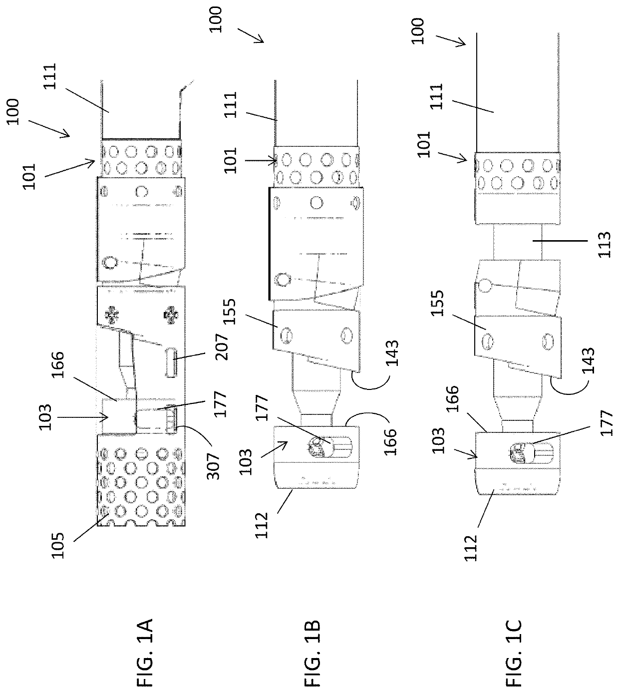
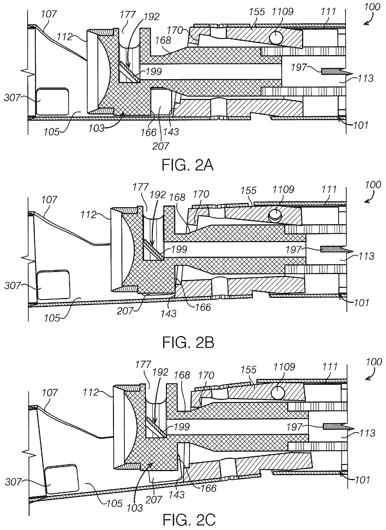
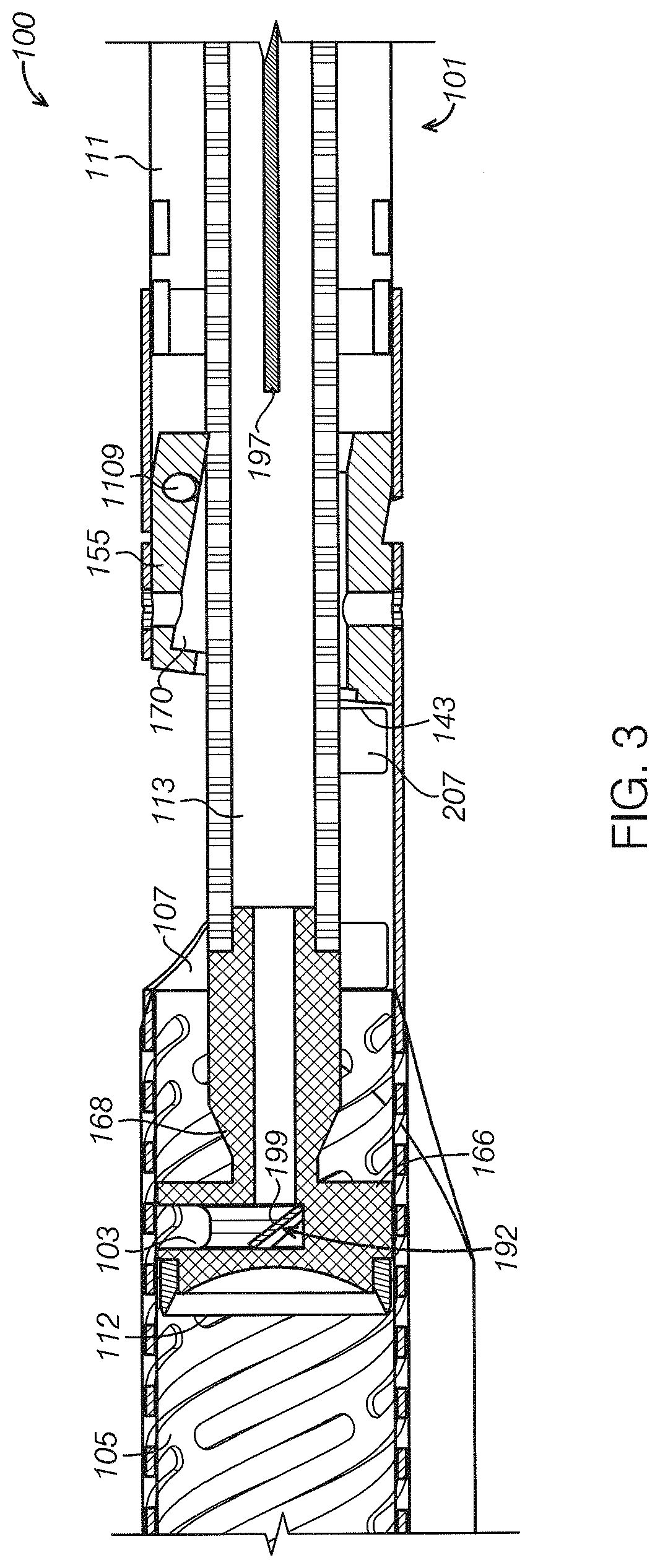
[0129]Described herein are atherectomy catheters and occlusion-crossing catheters. In general, the atherectomy catheters can include a rotatable cutter connected to a drive shaft. Further, the atherectomy catheters can include on-board imaging, such as optical coherence tomography (OCT) imaging. The atherectomy catheters can include a distal housing (nosecone) configured to hold excised tissue. The drive shaft can be moved distally to pack the excised tissue into the nosecone.

[0130]The atherectomy catheters described herein can include a catheter shaft with a drive chassis on the end. The drive chassis includes a stout torque coil (“imaging torqueing coil” / drive shaft) for rotating an imaging element, a cutter, and an imaging optical fiber in the center of the torque coil. Both the imaging elements and the cutter can be part of a head that rotates with the driveshaft. The head can rotate in a single direction (e.g., clockwise). The head can further slide distally / proximally by pushi...


PUM


Abstract

An atherectomy catheter includes an elongate flexible catheter body, a cutter near the distal end of the catheter body, a drive shaft connected to the cutter and extending within the catheter body, an imaging element near the distal end of the catheter body.

Description

CROSS REFERENCE TO RELATED APPLICATIONS[0001]This application is a continuation-in-part of U.S. patent application Ser. No. 15 / 354,842, filed Nov. 17, 2016, titled “ATHERECTOMY CATHETERS AND OCCLUSION CROSSING DEVICES,” now U.S. Pat. No. 10,470,795, which is a continuation of U.S. patent application Ser. No. 15 / 076,568, filed Mar. 21, 2016, titled “ATHERECTOMY CATHETERS AND OCCLUSION CROSSING DEVICES,” now U.S. Pat. No. 9,498,247, which is a continuation-in-part of U.S. patent application Ser. No. 15 / 072,272, filed Mar. 16, 2016, titled “ATHERECTOMY CATHETERS DEVICES HAVING MULTI-CHANNEL BUSHINGS,” now U.S. Pat. No. 9,592,075, which is a continuation-in-part of International Patent Application No. PCT / US2015 / 034613, filed Feb. 5, 2015, titled “ATHERECTOMY CATHETERS AND OCCLUSION CROSSING DEVICES”, now International Publication No. WO 2015-120146, which claims priority to U.S. Provisional Patent Application No. 61 / 936,837, titled “ATHERECTOMY CATHETERS AND OCCLUSION CROSSING DEVICES,...

Claims


Application Information

Patent Timeline
Patent Type & Authority Patents(United States)
IPC IPC(8): A61B5/00A61B17/3207A61M25/00A61B90/00A61B17/12A61M25/10A61B17/22A61B17/00
CPCA61B17/320783A61B5/0066A61B5/0084A61B17/1204A61B17/12031A61B17/12109A61B17/12136A61B17/320725A61B17/320758A61B90/37A61M25/0043A61M25/0068A61M25/0074A61M25/0082A61M25/1002A61M25/1011A61B2017/00557A61B2017/00738A61B2017/22067A61B2017/22071A61B2017/320791A61B2090/3735A61B2017/22054A61B2017/00318A61B2017/320032A61B2090/3937A61B2090/3614A61B5/02007A61B5/6853
Inventor PATEL, HIMANSHU N.SIMPSON, JOHN B.FERNANDEZ, ANTHONY J.NEWHAUSER, RICHARD R.GUPTA, PRIYANSHUZUNG, MICHAELLAM, WENDY NGOSPENCER, MAEGAN K.SMITH, PETER HOWARDDAVIES, STEPHEN C.SPINELLI, NICHOLAS J.MCNALL, CHARLES W.KETAI, THEODORE W.KANKARIA, MANISHASKEW, MARK W.STALKER, KENT C. B.
Owner AVINGER
Why Eureka
Try Eureka