Inkjet image forming apparatus and cleaning method for inkjet image forming apparatus

a technology of inkjet image and forming apparatus, which is applied in the direction of printing, etc., can solve the problems of short replacement cycle of mist-absorbing material for absorbing ink mist generated during the flushing process, and increase the amount of ink

Active Publication Date: 2016-11-29
RISO KAGAKU CORP
View PDF8 Cites 1 Cited by
  • Summary
  • Abstract
  • Description
  • Claims
  • Application Information

AI Technical Summary

Benefits of technology

[0007]However, in the above-mentioned ink-jet recording apparatus, consumption of ink increases due to an increase of an amount of ink used in the flush process, and a replacement cycle of a mist-absorbing material for absorbing ink mists generated during the flush process becomes short.
[0008]An object of the present invention is to provide an inkjet image forming apparatus and a cleaning method for the apparatus that can prevent increase of an amount of ink used in a flush process and can prolong a replacement cycle of a mist-absorbing material.

Problems solved by technology

However, in the above-mentioned ink-jet recording apparatus, consumption of ink increases due to an increase of an amount of ink used in the flush process, and a replacement cycle of a mist-absorbing material for absorbing ink mists generated during the flush process becomes short.

Method used


Image

  • Inkjet image forming apparatus and cleaning method for inkjet image forming apparatus
  • Inkjet image forming apparatus and cleaning method for inkjet image forming apparatus
  • Inkjet image forming apparatus and cleaning method for inkjet image forming apparatus

Examples


first embodiment

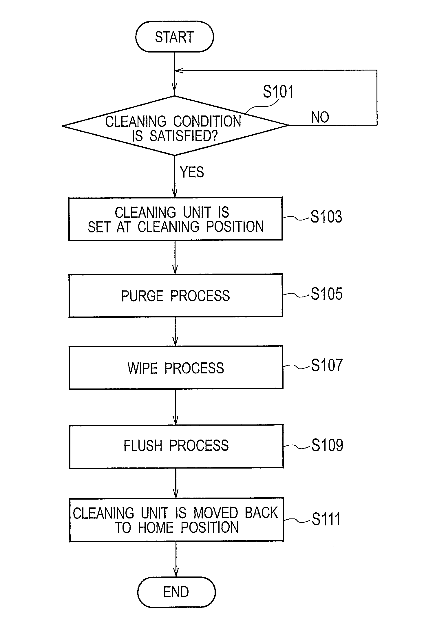
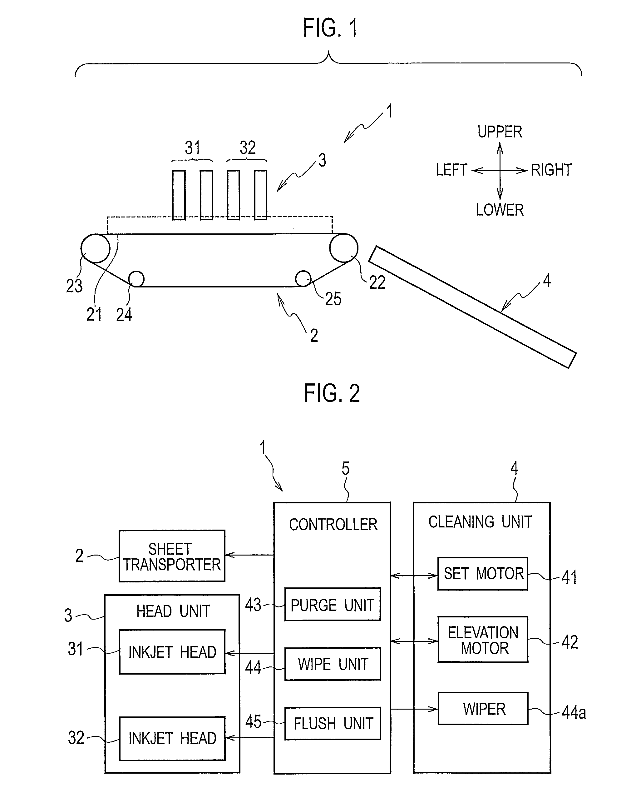
[0030]As shown in FIG. 1 and FIG. 2, an inkjet image forming apparatus 1 according to the present embodiment includes a sheet transfer unit 2, a head unit 3, a cleaning unit 4, and a controller 5.

[0031]The sheet transfer unit 2 includes a transfer belt 21 disposed so as to face to the head unit 3, a drive roller 22 that drives the transfer belt 21 circularly, and driven rollers 23 to 25 that are driven by the drive roller 22 via the transfer belt 21.

[0032]The transfer belt 21 is wound around the drive roller 22 and the driven rollers 23 to 25, and driven by the drive roller 22 endlessly during printing. The transfer belt 21 transfers a sheet (print paper) P fed from a sheet supply tray (not shown in the drawings) disposed on a left side in FIG. 1 to the head unit 3 (i.e. transfers the sheet P forward: rightward in FIG. 1).

[0033]The sheet transfer unit 2 can be moved vertically by an elevation motor 42 (see FIG. 2) to (1) a print position where the sheet transfer unit 2 executes a tr...

second embodiment

[0063]In the present embodiment, the wipers 44a are inclined with respect to the secondary sweep direction (transfer direction) in order to reduce an amount of ink injected in the flush process (i.e. consumption of ink in the flush process) further.

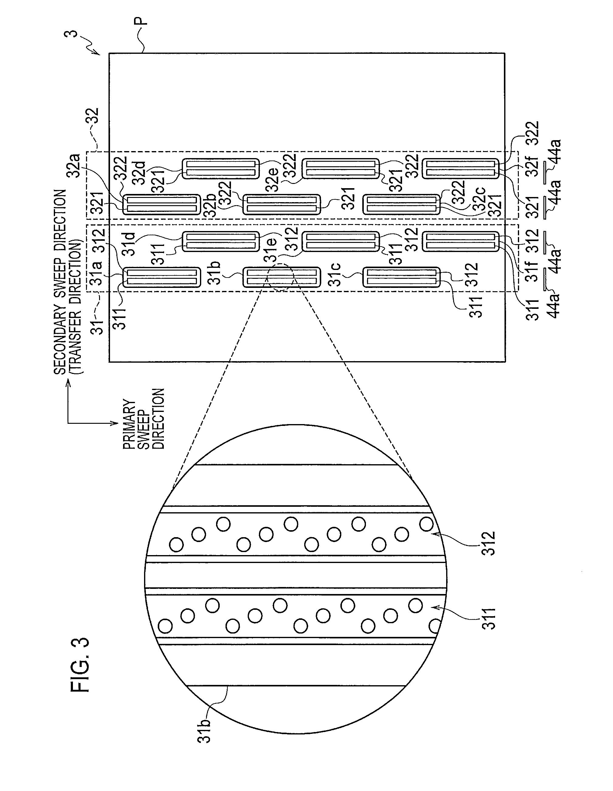
[0064]As shown in FIG. 12, all the wipers 44a are inclined so as to be parallel to each other. The wipers 44a are provided for a row of the inkjet heads 31a to 31c, a row of the inkjet heads 31d to 31f, a row of inkjet heads 32a to 32c, and a row of the inkjet heads 32d to 32f. Namely, the wipers 44a are inclined with respect to the rows. The wipe process is carried out as shown in FIGS. 13A and 13B (explained by taking the inkjet head 32a as an example).

[0065]By inclining the wipers 44a, purged ink droplets are wiped away to a constant side (rightward in FIG. 12) regardless of a state of the purged ink droplets. In the present embodiment shown in FIG. 12, ink droplets are wiped from a side of the nozzle row 311 of black (K) ink to a side...

third embodiment

[0070]In the present embodiment, the wipers 44a are inclined with respect to the secondary sweep direction (transfer direction) in order to reduce an amount of ink injected in the flush process (i.e. consumption of ink in the flush process) further, similarly to the above-described second embodiment. However, in the present embodiment, inclinations of the two wipers 44a in each of the inkjet heads 31 and 32 are different from each other as shown in FIG. 14. In a case where all the wipers 44a are inclined so as to be parallel to each other as in the above-described second embodiment, flushing is carried out only for one of the nozzle rows. Therefore, ink for the one of the nozzle rows is consumed more than ink for another of the nozzle rows. In the present embodiment, ink consumption is averaged with respect to all colors.

[0071]With respect to the inkjet head 31 that has two rows of inkjet heads 31a to 31f, the wiper 44a for the row of the inkjet heads 31a to 31c and the wiper 44a fo...


PUM


Abstract

An inkjet image forming apparatus includes inkjet heads each of which has two or more nozzle rows from which ink of different colors is injected (each of the nozzle rows includes nozzle holes), a wipe unit that includes wipers and carries out a wipe process to wipe away ink remained on a surface on which the nozzle rows are formed by the wipers, and a flush unit that carries out a flush process after the wipe process by injecting ink from nozzle holes into which ink of different color from color of ink that is injected from the nozzle holes flows during the wipe process. According to the apparatus, an amount of ink consumed in the flush process can be reduced and a replacement cycle of a mist-absorbing material for absorbing ink mists generated during the flush process can be prolonged.

Description

BACKGROUND OF THE INVENTION[0001]Technical Field[0002]The present invention relates to an inkjet image forming apparatus and to a cleaning method therefor.[0003]Background Arts[0004]A cleaning operation is done as one of cleaning operations in an inkjet image forming apparatus in order to keep proper ink injections from inkjet heads. In such a cleaning operation, (1) a purge process in which inks are forcibly injected from ink injection surfaces of inkjet heads, (2) a wipe process in which dusts attached onto the ink injection surface is wiped out by a wiper blade or the like together with inks remained on the ink injection surface is done, and (3) a flush process in which mixed inks staying in nozzles are forcibly injected out, are done sequentially.[0005]A Patent Document 1 (Japanese Patent Application Publication No. 2000-233518) discloses an “ink jet recoding apparatus” that includes inkjet heads for forming dots on a record medium by injecting ink droplets from nozzles accordin...

Claims


Application Information

Patent Timeline
Patent Type & Authority Patents(United States)
IPC IPC(8): B41J2/165
CPCB41J2/16535B41J2/16538B41J2/16544
Inventor UJIIE, HIDEYUKIAKIYAMA, TOMOYUKISUGITANI, HIROSHI
Owner RISO KAGAKU CORP
Why Eureka
Try Eureka