Single-pole switching unit and switching unit comprising one such unit

a single-pole switching unit and switching unit technology, applied in the direction of circuit-breaking switches, circuit-breaking switches for excess current, high-tension/heavy-dress switches, etc., can solve the problems of preventing multiple operation of devices, obstructing the channel, etc., and achieves the effect of quick triggering and avoiding obstruction of the channel

Active Publication Date: 2016-11-29
SCHNEIDER ELECTRIC IND SAS
View PDF9 Cites 5 Cited by
  • Summary
  • Abstract
  • Description
  • Claims
  • Application Information

AI Technical Summary

Benefits of technology

[0009]The present invention aims to resolve this drawback, by proposing a single-pole switching unit with a rotating gate both enabling quick triggering and avoiding obstruction of the channel after discharge of the gases.
[0016]Advantageously, in the triggering position, the rotating gate reaches an opening position of the exhaust channel, which allows better discharge of the switching gases and avoids any obstruction of the channel.

Problems solved by technology

With this known rotating gate, solid debris builds up in the gas discharge channel, causing obstruction of the channel and preventing the operation of the device multiple times.

Method used


Image

  • Single-pole switching unit and switching unit comprising one such unit
  • Single-pole switching unit and switching unit comprising one such unit
  • Single-pole switching unit and switching unit comprising one such unit

Examples


Embodiment Construction

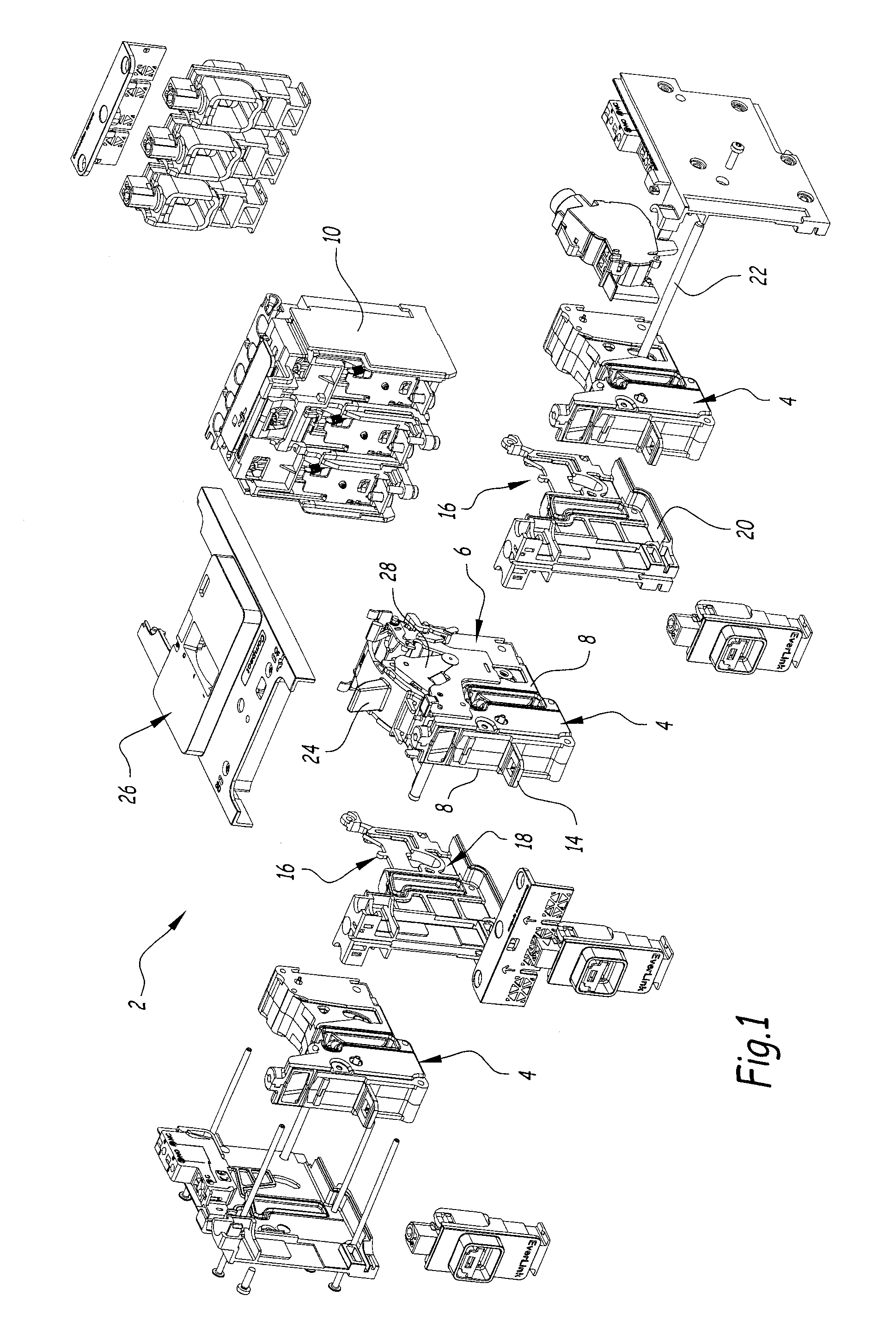
[0034]FIG. 1 shows an example electric switching unit 2 in an exploded perspective illustration, comprising three single-pole switching units 4.

[0035]According to other embodiments that are not shown, the cutoff apparatus may comprise one, two, three or four single-pole switching units.

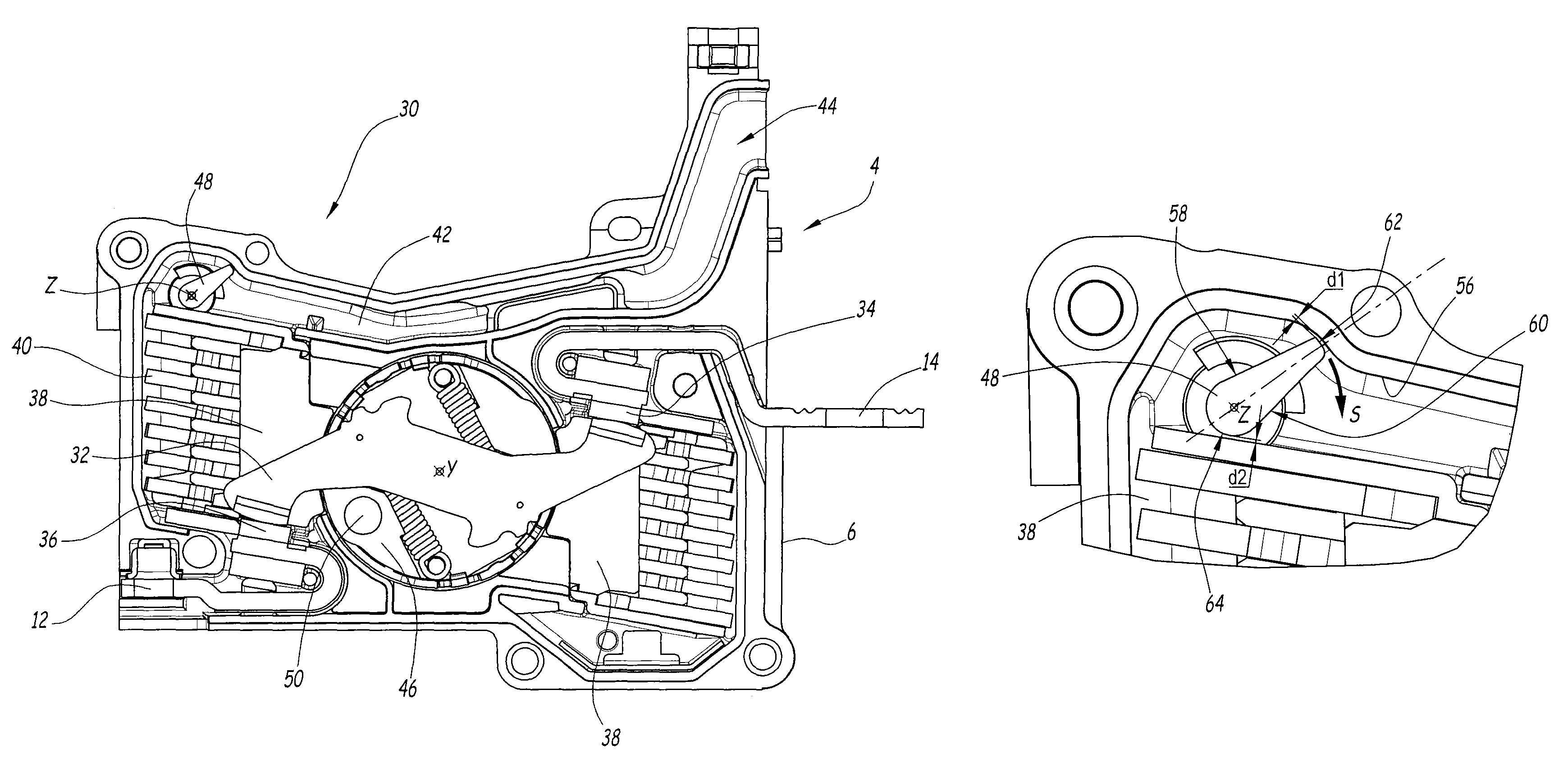
[0036]Each single-pole switching unit 4 makes it possible to cut off a single pole. Each switching unit assumes the form of a flat housing 6, for example made from molded plastic, formed from two large parallel faces 8, separated by a thickness of approximately 23 millimeters (mm) for a caliber of 160 Amperes (A). The housing is preferably formed by two mirror-image symmetrical parts, secured by any suitable means.

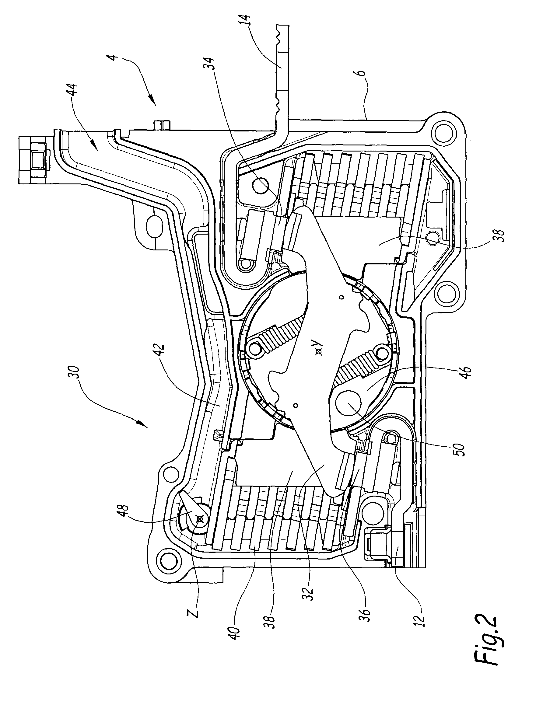
[0037]Each single-pole switching unit is connected to a triggering unit 10, able to comprise magnetothermal means or electronic means, at a downstream contact area 12 (see FIG. 2) as well as to a current line connected to an upstream contact area 14.

[0038]In the embodiment illustrated in FIG...


PUM


Abstract

The invention relates to a single-pole switching unit having a housing comprising a moving contact bridge and a pair of fixed contacts cooperating with said moving contact bridge and respectively connected to a current intake conductor, two electric arc cutoff chambers respectively opening onto an open volume of the moving contact bridge, each cutoff chamber being connected to at least one exhaust channel (42). The exhaust channel (42) comprises a rotating gate (48) designed to be rotated around an axis substantially perpendicular to the exhaust channel (42) by the passage of switching gases. The rotating gate (48) comprises an edge (54) positioned across from an inner wall (56) of the exhaust channel, in the first obstruction position. The arrangement of the rotating gate (48) and the inner wall (56) is such that the distance between said edge (54) and said inner wall (56) remains constant and equal to said first distance up to a first threshold value of the angle of rotation of the rotating gate (48), then increases linearly up to a second rotation angle threshold value corresponding to complete opening of the discharge channel. The invention also relates to a switching unit comprising at least one single-pole switching unit.

Description

BACKGROUND ON THE INVENTION[0001]The present invention relates to a single-pole switching unit. It also relates to a switching unit comprising at least one single-pole switching unit.[0002]It belongs to the field of switching units, in particular high-power, low-voltage circuit breakers, in which the discharge of the switching gases is used to trigger a current switching mechanism.[0003]In such switching units, it is necessary to trigger the mechanism opening the circuit breaker once an arc appears in the cutoff chamber.[0004]Various solutions have been proposed to achieve quick triggering.[0005]Patent application FR2986659 describes a modular switching unit, comprising improved pneumatic triggering means.[0006]This document describes a switching unit comprising at least one single-pole switching unit, and preferably three single-pole switching units, each single-pole switching unit being connected to a triggering unit at a downstream contact. Each single-pole switching unit also co...

Claims


Application Information

Patent Timeline
Patent Type & Authority Patents(United States)
IPC IPC(8): H01H33/86H01H77/02H01H33/73H01H9/34
CPCH01H33/86H01H9/342H01H33/73H01H77/02H01H2009/343H01H2077/025
Inventor LEGENDRE, PHILIPPEGONNET, JEAN-PAULGIRAUD, DENIS
Owner SCHNEIDER ELECTRIC IND SAS
Why Eureka
Try Eureka