Sound diverter

a diverter and sound technology, applied in the field of sound diverters, can solve the problem that poor sound cannot be qualified to the end user, and achieve the effect of reducing the number of sound sources

Active Publication Date: 2016-11-29
B A N ENTERPRISES
View PDF6 Cites 2 Cited by
  • Summary
  • Abstract
  • Description
  • Claims
  • Application Information

AI Technical Summary

Benefits of technology

[0004]It is an object of the instant invention to provide a novel sound diverter that acts to enhance sound emanating from an electronic device, particularly a flat screen television, containing one or more speakers in the side, top or bottom of its housing.
[0006]The sound diverter according to the present invention is an improvement over the art in providing a universal adaptable configuration to permit useful adaptation to a plurality of electronic device configurations, such as, but not by way of limitation, multiple modern flat LCD or LED screen televisions having a thin profile containing a speaker in a side, top or bottom of its housing, in combination with the sound diverter to enhance the volume and quality of the sound from the speaker.
[0007]The sound diverter includes a longitudinal member connected by way of breakable tabs to a ledge having a concave surface extending inwardly therefrom and which is for disposal adjacent the speaker of an electronic device for diverting sound from the speaker. There is at least one, and preferable two, recessed surfaces laterally extending from the ledge on either side of the concave surface. Depending on the configuration of the particular electronic device, e.g., t.v., to which the sound diverter is to be attached, either the longitudinal member, recessed surfaces or both can be used for attaching the sound diverter to the electronic device. A removable connector can be employed which interconnects the longitudinal member and back of the electronic device. In one configuration, the removable connector can include a hook and loop member adhesively connected to the longitudinal member and the back of the electronic device with the ledge disposed about a speaker having the concave surface extending over the speaker leaving an open end of the concave surface facing forward. In another configuration in order that the concave be placed over the speaker, it may require the longitudinal member be snapped off at the tabs thereby enabling positioning over the speaker and in this configuration hook and loop member, for example, adhesively interconnects the recessed surfaces to an edge of the t.v., such that the concave surface is over the speaker leaving an open end of the concave surface facing forward. Note that the recessed surfaces in combination with the removable connector permit the ledge to remain relatively flush against the t.v. edge surface. The connection may be done by hook and loop or other removably connectable means. Note, the performance of the sound diverter is enhanced by maintaining the ledge of the sound diverter against the surface of the device thereby maximizing the deflection of the sound waves off the concave surface. The incorporation of magnetic coupling is recognized as one means to enhance the sound reflection. In so providing, there is apparent amplification of sound from the speaker of the electronic device achieved by confining the sound energy within and through the sound diverter with the sound energy emerging at the open end of the sound diverter.
[0009]It is further contemplated that there can be provided a double sided foam tape configured to sealably interconnect the longitudinal or ledge to the electronic device, but that hard surface to surface connections may perform better as they do not absorb any sound wave.

Problems solved by technology

This has resulted in poorer sound qualify to the end user.

Method used


Image

  • Sound diverter
  • Sound diverter

Examples


Embodiment Construction

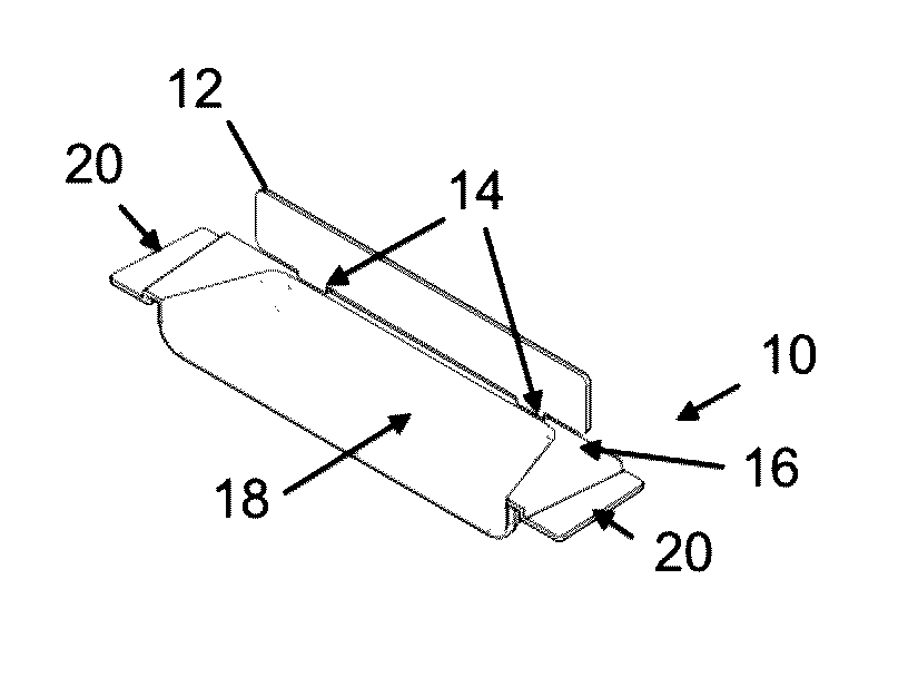
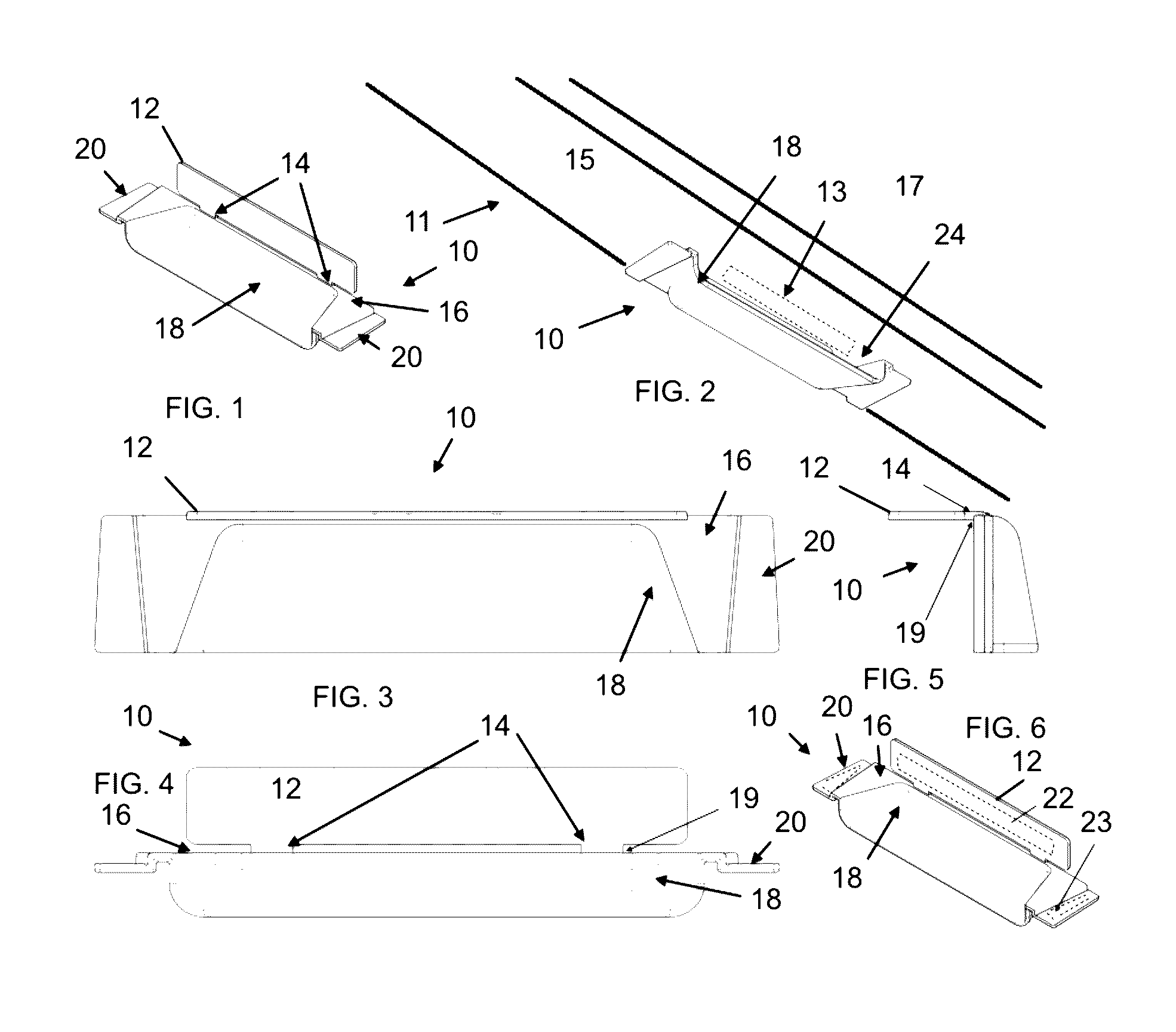
[0016]Referring now to the drawings, the present invention relates a sound diverter which is generally referred to by the numeral 10. The sound diverter 10 is an improvement over the art in providing a universal adaptable configuration to permit useful adaptation to a plurality of electronic devices, such as, but not by way of limitation, modern flat LCD or LED screen television 11 having a thin profile containing a speaker 13 in a side, top or bottom of a housing 15, which in combination with the sound diverter 10 to enhance the volume and quality of the sound from the speaker 13.

[0017]The sound diverter 10 can preferably be made of plastic, such as polypropylene, polyethylene, or PVC, although other plastic materials, such as polycarbonate compounds, metal, for example. The sound diverter 10 has a longitudinal member 12 connected by way of one or more breakable tabs 14 having a break portion 19 connecting to a ledge 16. The ledge 16 has a concave surface 18 extending inwardly ther...


PUM


Abstract

A sound diverter for use with an electronic device which has one or more speakers, wherein the sound diverter is operably connected to the device enhancing the sound emitted from the speaker.

Description

FIELD OF INVENTION[0001]The present invention relates a sound diverter for use with electronic devices. More particularly, the sound diverter of the instant invention is an improvement over the art in proving a universal adaptable configuration to permit useful adaptation to a plurality of electronic devices, such as, but not by way of limitation, numerous modern flat LCD or LED screen televisions having a thin profile containing a speaker in a side, top or bottom of its housing, in combination with the sound diverter to enhance the volume and quality of the sound from the speaker.BACKGROUND OF INVENTION[0002]As the current electronic screen devices have continuously sought to streamline their design into thinner configurations and maximizing screen size, they have integrated speakers into the back, top, bottom or sides of the television unit. This has resulted in poorer sound qualify to the end user.[0003]Accordingly, there are various sound reflector products which have been inven...

Claims


Application Information

Patent Timeline
Patent Type & Authority Patents(United States)
IPC IPC(8): H04R25/00H04R1/02H04R1/34
CPCH04R1/028H04R1/345H04R2499/15
Inventor NEWMAN, BRET ARDEN
Owner B A N ENTERPRISES
Why Eureka
Try Eureka