Apparatus for counterbalancing a rotating arm in an imaging system

a technology of rotating arms and imaging systems, applied in the field of imaging apparatuses, can solve the problems of significant torque to be applied, increase the power requirement of the actuation system (motor, gear, etc.), and add significantly to the weight and cost of the system

Active Publication Date: 2016-12-06
GENERAL ELECTRIC CO
View PDF12 Cites 5 Cited by
  • Summary
  • Abstract
  • Description
  • Claims
  • Application Information

AI Technical Summary

Benefits of technology

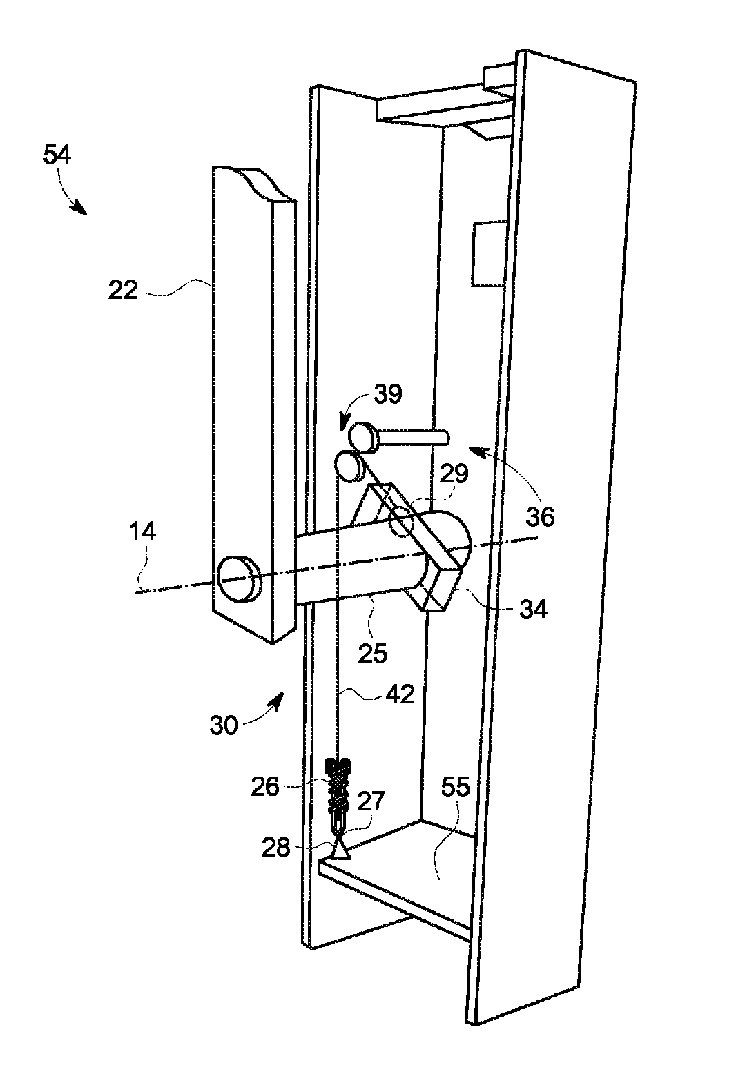
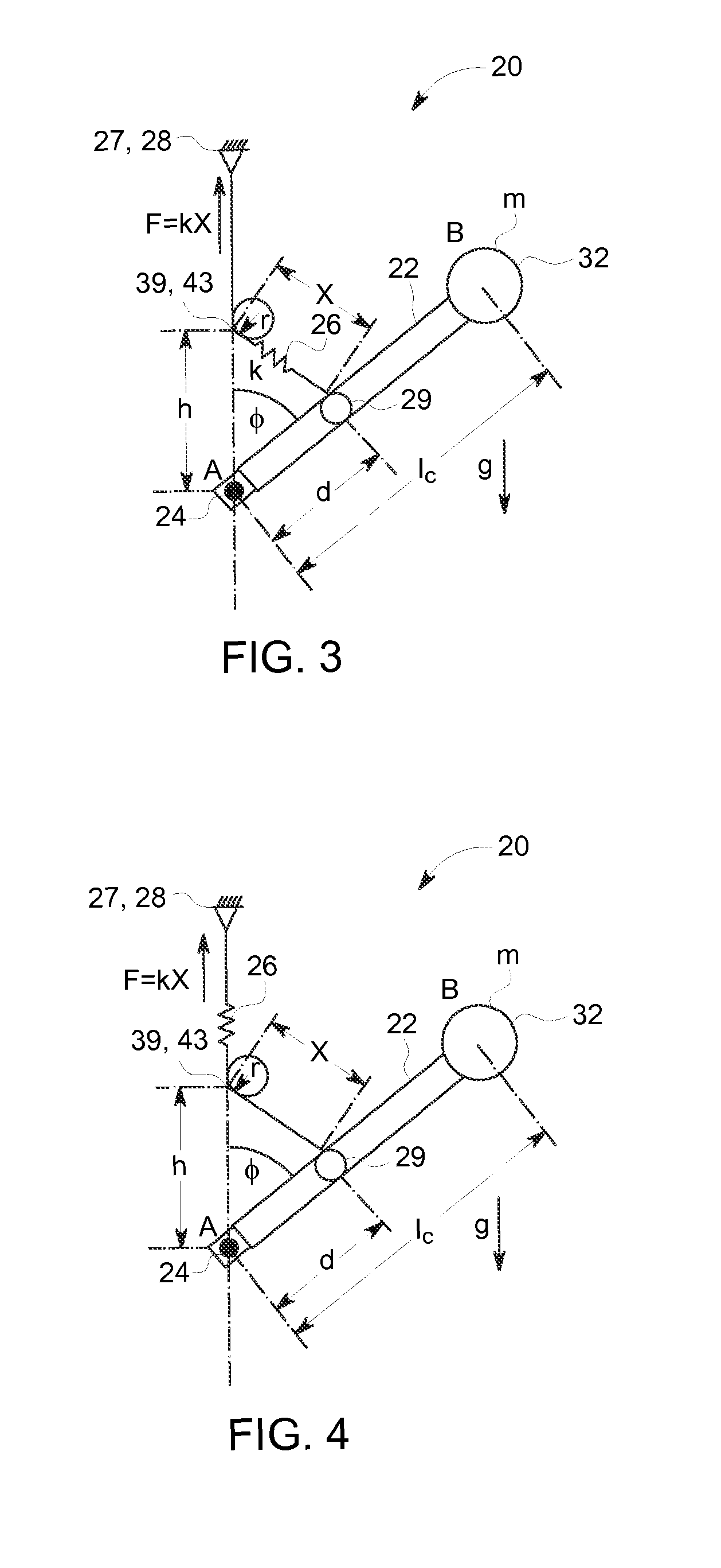
[0011]In yet another aspect, a mammography system is provided. The mammography system including a base support, an arm coupled to a rotating component for rotating a body having a mass “m” relative to the base support about an axis of rotation, an extender arm configured parallel to the arm and coupled to the rotating component for rotating relative to the base support about the axis of rotation and a balancing system. The rotating component is coupled to the base support. The balancing system includes a spring mechanism coupled to the base support and to an active connection point located on the extender arm between the axis of rotation of the arm and the body via a geometric constraining point. The active connection point is located a distance “d” from the pivot point. The geometric constraining point is located a distance “h” from the pivot point. As the arm is rotated about the axis of rotation, the balancing system synchronizes the angle of rotation of the arm with the angle of rotation of the extender arm such that the applied force of the spring mechanism counteracts the torque force of the arm to statically balance the system and provide f=kX, where f is the force of the spring, k is a spring rate of the spring mechanism and x is a distance between the active connection point and the geometric constraining point.

Problems solved by technology

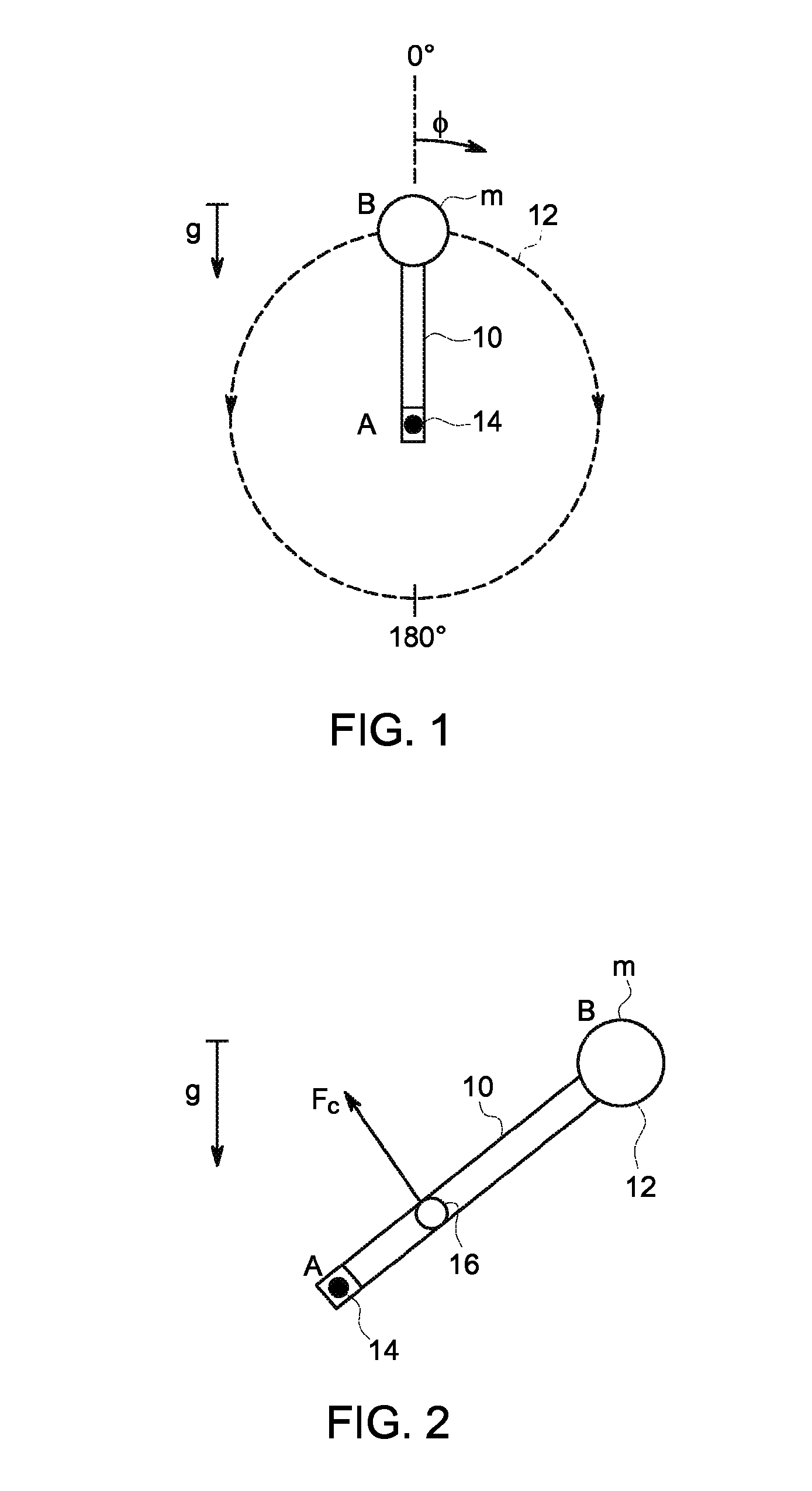
For construction reasons, and due to the varying weights of the components, the center of mass of the rotatable C-arm is typically spaced apart from the axis of rotation, and is therefore “unbalanced” about the axis of lateral rotation.
In an unbalanced system, a significant torque must be applied to rotate the arm to a desired position.
These counterbalance mechanisms used in mammography systems balance the gravitational torque of the rotating arm only partially, leading to much higher power requirement of the actuation system (motor, gear, etc.).
While counterweights significantly reduce the torsional force that must be applied when rotating the arm, they add significantly to both the weight and cost of the system.
Furthermore, the counterweights make it very difficult to move the mammography system from place to place when desired.
Such a mechanism may only partially balance the arm.
In addition, it is estimated that the gas spring force can degrade up to 20% over its lifespan and has very limited cycle life.
Accordingly, the use of a gas spring limits the fatigue life of the system and increases the need for service.

Method used


Image

  • Apparatus for counterbalancing a rotating arm in an imaging system
  • Apparatus for counterbalancing a rotating arm in an imaging system
  • Apparatus for counterbalancing a rotating arm in an imaging system

Examples


Embodiment Construction

[0024]The exemplary methods and systems described herein overcome the structural disadvantages of known imaging systems by providing a balancing system that reduces the torque required for rotation of arm having mounted thereto at least one of an X-ray source or an X-ray detector. Each example is provided by way of explanation of the disclosure, not limitation of the disclosure. In fact, it will be apparent to those skilled in the art that modifications and variations can be made in the present disclosure without departing from the scope or spirit thereof. For instance, features illustrated or described as part of one embodiment may be used on another embodiment to yield a still further embodiment. Thus, it is intended that the present disclosure covers such modifications and variations as come within the scope of the appended claims and their equivalents. Although exemplary embodiments of the present disclosure will be described generally in the context of a mammography system for ...


PUM


Abstract

An apparatus for balancing a statically unbalanced system, particularly useful in balancing X-ray and mammography systems having an X-ray source and detector mounted to a rotational arm, includes a spring mechanism which synchronizes the activation of the spring mechanism with the rotation of the arm of the mammography system. The balancing system reduces the amount of torque necessary to rotate the arm and decreases the overall inertia of the system by eliminating the need for counterweights to maintain balance of the system.

Description

BACKGROUND[0001]The embodiments described herein relate generally to imaging apparatuses, and more specifically, to an apparatus including at least one of an X-ray source and X-ray detector mounted to a rotational arm.[0002]In a number of clinical applications, imaging apparatus, and more particularly X-ray apparatuses, which include an X-ray source and X-ray detector mounted to a rotational arm are common These systems provide the ability to rotate the X-ray source and detector to varying angles to obtain images without requiring the patient to move. A mammography system, for example, typically comprises an X-ray source, an X-ray detector, a breast support plate, and a breast compression plate. The source and detector are mounted to opposing ends of an arm, such as a C-arm, and the arm is disposed to rotate around the breast support and compression plates. The breast is positioned between the breast support and breast compression plates to hold the breast in place during mammograph...

Claims


Application Information

Patent Timeline
Patent Type & Authority Patents(United States)
IPC IPC(8): A61B6/00F16M11/04
CPCA61B6/4441A61B6/447A61B6/502F16M11/04
Inventor MAO, YINGMOULIN, ROMAIN
Owner GENERAL ELECTRIC CO
Why Eureka
Try Eureka