Cycle with single wheel

a technology of single wheels and bicycles, applied in the direction of bicycles, wheel-based transmissions, transportation and packaging, etc., can solve the problems of difficult product production and complicated shifting, and achieve the effects of preventing dirt from flowing, stable posture, and convenient riding

Inactive Publication Date: 2016-12-06
GO JONG HWA
View PDF15 Cites 3 Cited by
  • Summary
  • Abstract
  • Description
  • Claims
  • Application Information

AI Technical Summary

Benefits of technology

[0009]According to an embodiment of the present invention, first, it is possible to maintain a stable posture by distributing the weight of a rider under the center of a wheel to achieve a cycle with a single wheel that is easy to ride and can be efficiently driven.
[0010]Second, it is possible to easily transmit a driving force by positioning a pedal shaft ahead of the center of the wheel, have a large rotation ratio using gears, coast using a free wheel, provide time space for balancing, and easily handle operation of a brake.
[0011]Third, it is possible to prevent dirt from flowing into a driving unit or prevent the clothes of a rider pressing down a pedal being stuck in the driving unit.

Problems solved by technology

However, the technology described above provides a structure essential to exhibit the principle of the invention, but shifting is complicated and it is difficult to make in a product.

Method used


Image

  • Cycle with single wheel
  • Cycle with single wheel
  • Cycle with single wheel

Examples


Embodiment Construction

[0032]Hereinafter, preferred embodiments of the present invention will be described with reference to accompanying drawings

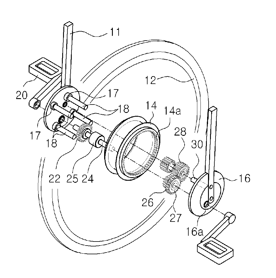
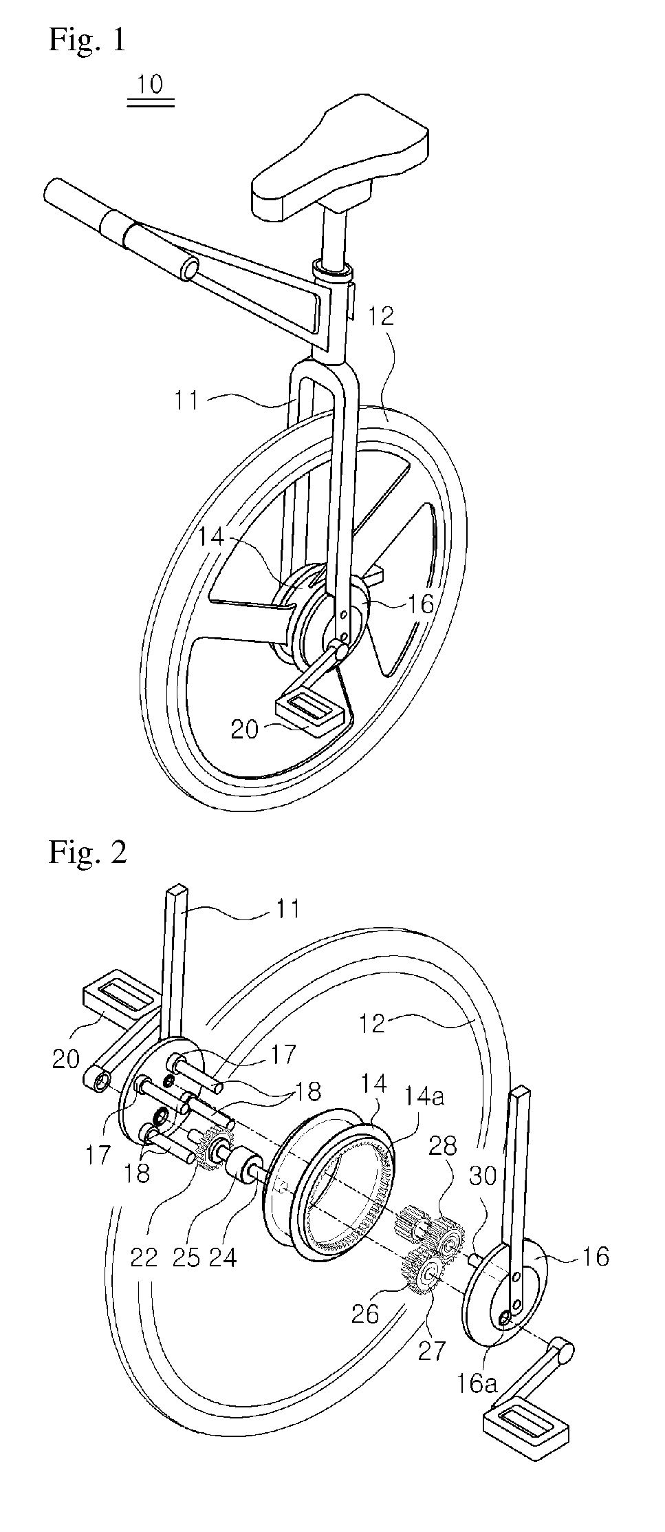
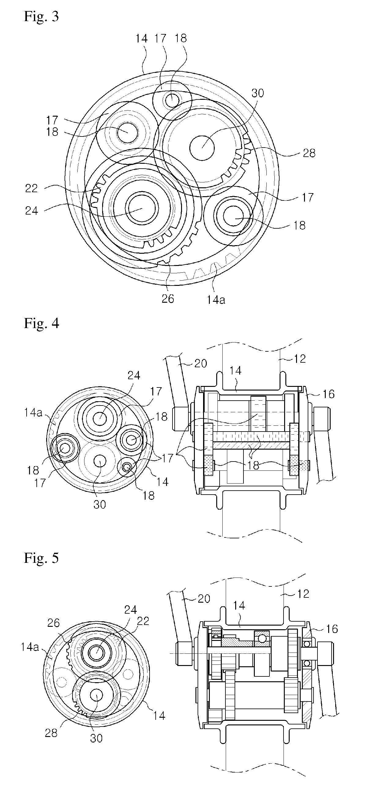
[0033]FIG. 1 is a perspective view of a cycle with a single wheel according to an embodiment of the present invention, FIG. 2 is an exploded perspective view of the cycle with a single wheel according to an embodiment of the present invention, FIG. 3 is a cross-sectional view of a hub illustrating arrangement of a pedal shaft, a gear shaft, and a roller shaft, gears fitted on the shafts, and the position of rollers illustrated in FIG. 2, and FIGS. 4 and 5 are a side projection view and a front projection view illustrating the structure of the present invention

[0034]As illustrated in FIG. 2, a cycle 10 with a single wheel according to an embodiment of the present invention includes a cycle body 11, a wheel 12, and a power generating unit.

[0035]The wheel 12 has a hub 14 at the center. A space where at least the power generating unit to be described below can be in...


PUM


Abstract

The present invention relates to a cycle with a single wheel, and a cycle with a single wheel according to the present invention includes: a wheel with a central hub; a roller contacting the inside surface of the hub with a plurality of roller shafts connected to both ends of the hub, the roller shafts being separated from each other with a given interval; a hub cover with the outside connected to the end part of a cycle body; a gear shaft provided with a first multi-stage gear and connected to the hub cover so as to be positioned between the plurality of roller shafts; and a pedal shaft inserted through a hole formed in a given position of the hub cover so as to penetrate the hub, wherein the pedal shaft is mounted with a gear engaging with one end of the first multi-stage gear, and a second multi-stage gear is inserted with one end thereof spaced from the gear to engage with the other end of the first multi-stage gear and the other end thereof engaging with a gear part formed in the inner peripheral surface of the hub, so that a drive force generated by the pedal is transferred through the gear mounted on the pedal shaft to the first multi-stage gear, and the drive force transferred to the first multi-stage gear is transferred through the second multi-stage gear to the gear part, thus rotating the wheel.

Description

RELATED APPLICATIONS[0001]The present application is the U.S. national phase entry of PCT / KR2014 / 003343, with an international filing date of Apr. 17, 2014, which claims the benefit of Korean Patent Application No. 10-2013-0042581, filed Apr. 18, 2013, the entire disclosures of which are incorporated herein by reference.TECHNICAL FIELD[0002]The present invention relates to a cycle with a single wheel, in detail, a cycle with a single wheel that easily transmits a driving force by distributing and transmitting the center of gravity of a rider under the center of the wheel with a pedal shaft at a front portion of the wheel.BACKGROUND ART[0003]A “Ssing sing barqeui” has been disclosed in Korean Patent Application Publication No. 10-2009-0086194. The related art is characterized in that, in order to solve the problem that a rider cannot maintain a stable posture on a bicycle in which gravity applied to a saddle disposed outside an outer wheel is transmitted to a point of the center of a...

Claims


Application Information

Patent Timeline
Patent Type & Authority Patents(United States)
IPC IPC(8): B62M11/02B62K1/00B62M1/38
CPCB62M11/02B62K1/00B62M1/38
Inventor GO, JONG HWA
Owner GO JONG HWA
Why Eureka
Try Eureka