
Loads management and outages detection for smart grid

a smart grid and load technology, applied in powerline communications applications, instruments, heat measurement, etc., can solve the problems of even bigger problems, lack of information, and lack of information about currents at the splitting points off the outgoing line, and achieve the effect of cheap, rapid and easy rms current measuremen

Active Publication Date: 2016-12-06
GOLDWINGS S G LTD
View PDF11 Cites 12 Cited by
  • Summary
  • Abstract
  • Description
  • Claims
  • Application Information

AI Technical Summary

Benefits of technology

The system provides accurate, real-time current measurements and rapid outage detection, allowing for improved load management and voltage regulation, reducing the need for costly network changes and enhancing operational efficiency.

Problems solved by technology

But there is always a lack of information at the splitting points of transmission lines where there is more than one substation connected on the line.
There is also a lack of information about the currents at the splitting points off the outgoing lines of the distribution transformers, feeding large number of secondary lines in urban areas.
The problem is even bigger at urban areas where low voltage lines supply electric power to small businesses and residents and many customers are connected to branches of the same power line, and they depends each other in their power consumption influencing their mutual voltage levels.
The control systems cannot detect such local variations in current and voltage levels usually compensated by other branches of the line.
Another problem of the electric grid control is to detect rapidly an outage and its location.
It is hard to know, especially in bad weather conditions in winter and / or at night that one or more lines are ruptured (fallen trees on electric lines, electric towers prostrated by inundation etc.).
The lack of information about the current distribution in local networks results in lack of control means.
It happens very often that in such places power consumption is very high during some working hours of businesses, during the day, and very low at night.
As a result there is a big drop in voltage during the working hours and too high voltage levels at night.
Usually customers complains enable to detect such areas, but there is no means to control such phenomenon but a costly change in the network configuration, because the power control center usually has no on line information about these load changes to enable smart power back-up switching.
But there is no information on currents distribution in the network between the end users and the outputs of the substations to enable real and better load control and voltage level regulation.

Method used


Image

  • Loads management and outages detection for smart grid
  • Loads management and outages detection for smart grid
  • Loads management and outages detection for smart grid

Examples


Embodiment Construction

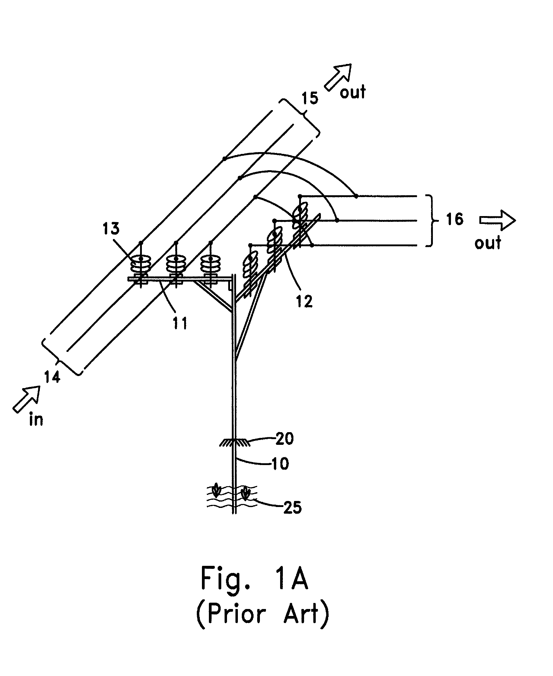
[0049]FIG. 1A schematically illustrates a typical concrete tubular electric lines pole 10 directly set in the earth 25, carrying two cross arms beams 11, 12, supporting with pin type insulators 13, an incoming three phase line conductors 14 (i.e., distribution line, supply transformer side) and two outgoing splitting lines 15, 16. Usually, such pole 10 may also comprises a safety lattice-type fence 20 for preventing the climbing of unauthorized persons on the pole. This embodiment shows an example of a concrete tubular pole with two splitting lines. Of course, the pole can be any type of tubular or other type of poles or electric lines towers carrying more than two cross arms beams or two outgoing splitting lines.

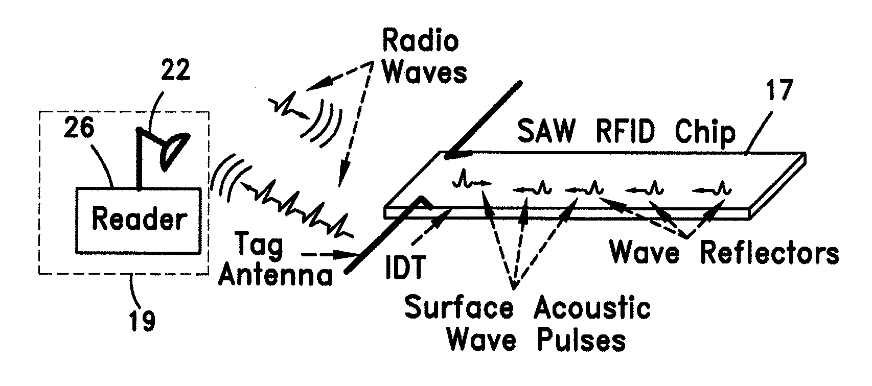
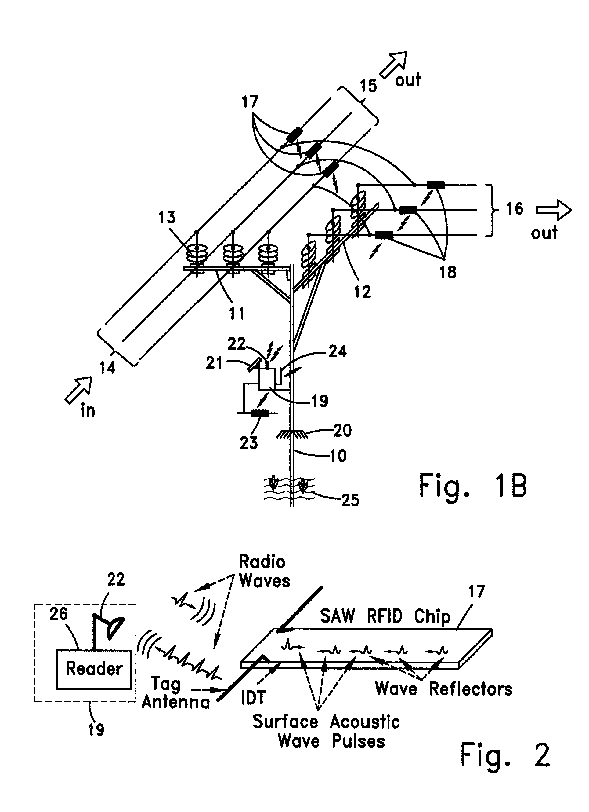
[0050]FIG. 1B schematically the typical pole 10 equipped with a smart grid system according to an embodiment of the present invention. The smart grid system comprises a Current Measuring Unit (CMU) 19 and one or more passive temperature Surface Acoustic Wave Radio Frequency...


PUM

PropertyMeasurementUnit
temperaturesaaaaaaaaaa

Abstract

A system for managing loads and detecting outages over electric power lines that comprises wireless temperature sensors which are attached to bare conductors of the electric power line(s), at line junctions or lines' splitting points, for sensing temperatures generated by the currents flow in the conductors. The system also includes a Current Measurement Units (CMU) for wirelessly reading the temperature sensed by the sensors, to allow cheap, rapid and easy RMS currents measurements on power lines at any voltage levels, by using temperature into current conversion formulas and tables.

Description

FIELD OF THE INVENTION[0001]The present invention relates to the field of Smart Grid loads and outages monitoring and management. More particularly, the invention relates to a method and system for creating cheap real time currents measurements, on power lines conductors.BACKGROUND OF THE INVENTION[0002]A smart grid delivers electricity from suppliers to customers using digital technology to save energy. This technology should also help to decrease peak demands of power, increase reliability and help to control voltage levels according to loads variations.[0003]Smart grid (also called: Smart Electric Grid, Smart Power Grid, Intelligent Grid, IntelliGrid, FutureGrid, Intergrid, Intragrid etc.), need more information to enable to operate the control means like additional windings of transformers used to change voltage levels, circuit breakers used to connect / disconnect loads or make by-pass connections to increase power supply from under loaded lines to overloaded lines in the network...

Claims


Application Information

Patent Timeline
Patent Type & Authority Patents(United States)
IPC IPC(8): G01R15/14G01K11/26G01R19/00
CPCG01K11/265G01R15/146G01R19/0092H04B2203/5458
Inventor HENIG, MOSHEYEGER, DOV
Owner GOLDWINGS S G LTD
Learn More