
Device and method for capturing X-ray image of bone-in meat and deboning system of bone-in meat including the device

a technology of bone-in meat and x-ray image, which is applied in the field of devices and methods for capturing x-ray image of bone-in meat and deboning system of bone-in meat including the device, can solve the problems of difficult to obtain accurate information related to a position of the bone or a shape of the bone in the bone-in meat, reducing the yield rate, and preventing the application of excessive load on the cutter. , the effect of improving the yield

Active Publication Date: 2016-12-06
MAYEKAWA MFG CO LTD
View PDF35 Cites 3 Cited by
  • Summary
  • Abstract
  • Description
  • Claims
  • Application Information

AI Technical Summary

Benefits of technology

The patent is about a method for making incisions in bone-in meat using X-ray images. The method improves the accuracy of the incision by adjusting the intensity distribution of the X-rays to match the shape of the bone. This reduces the chance of yield loss or excessive load on the cutter. The method also slows down the speed of the work, which improves processing ability. Overall, the method improves the efficiency and accuracy of incision making in bone-in meat.

Problems solved by technology

In a case where the X-ray image picked up with the stereotypical arrangement is used, it is difficult to acquire accurate information related to a position of the bone or a shape of the bone in the bone-in meat.
If an incision making is performed based on inaccurate information, a yield rate decreases because the trajectory of the cutter deviates from the bone and the meat remains on the bone, or an excessive load is applied to the cutter because the cutter cuts into the bone.
Specifically, in a case where the incision making is performed in a state where a work moves at high speed, the decrease of the yield rate or the excessive load of the cutter becomes remarkable.
Thus, it is necessary to slow down a moving speed of the work, and, as a result, ability of processing decreases.

Method used


Image

  • Device and method for capturing X-ray image of bone-in meat and deboning system of bone-in meat including the device
  • Device and method for capturing X-ray image of bone-in meat and deboning system of bone-in meat including the device
  • Device and method for capturing X-ray image of bone-in meat and deboning system of bone-in meat including the device

Examples


Embodiment Construction

[0107]The present invention will be described in detail by using embodiments shown in the drawings. However, it is to be noted that the scope of the present invention is not limited only to dimensions, materials, shapes, and relative arrangements of components described in the embodiments unless specifically described.

[0108][Entire Configuration of Deboning System]

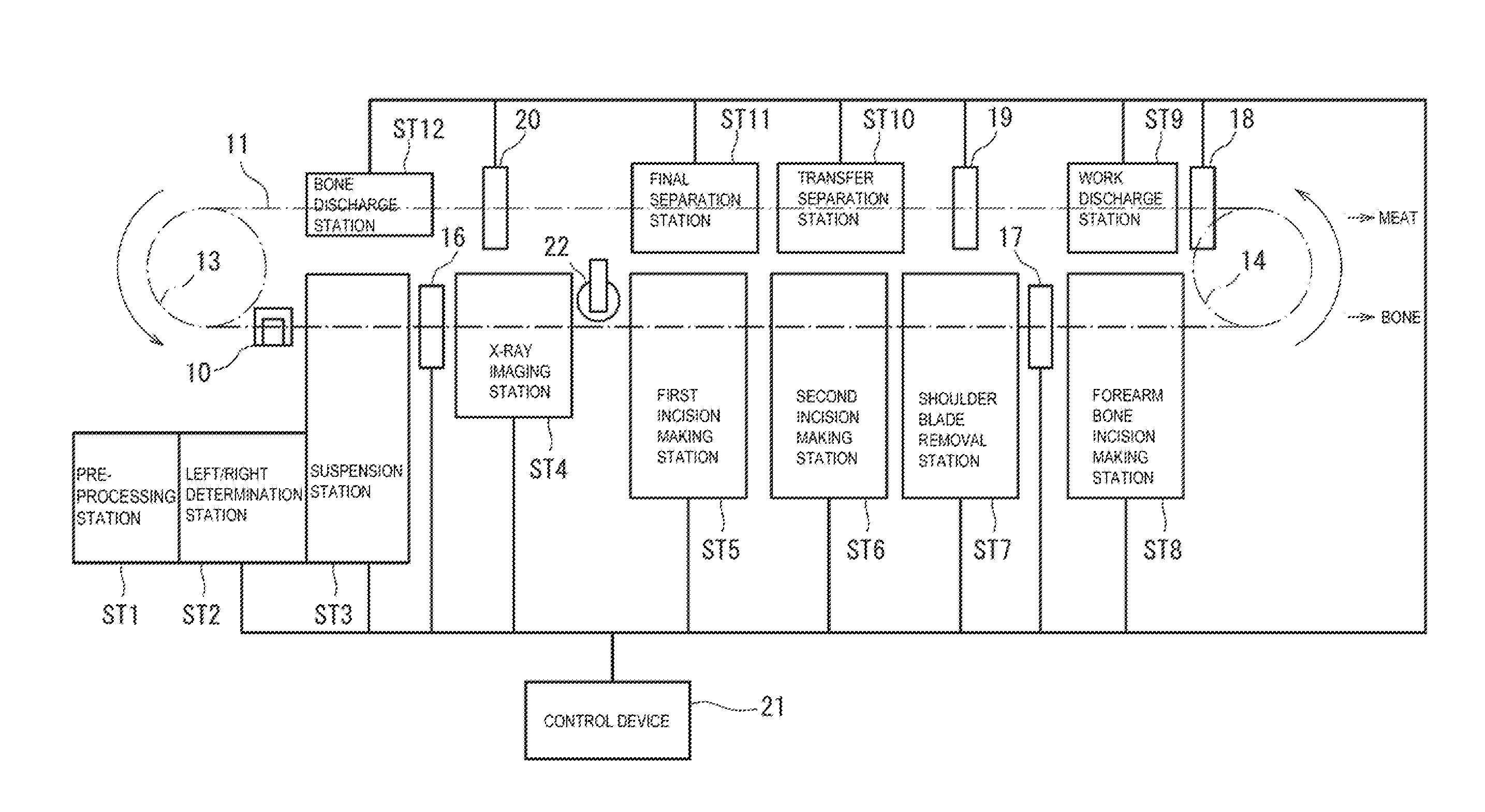
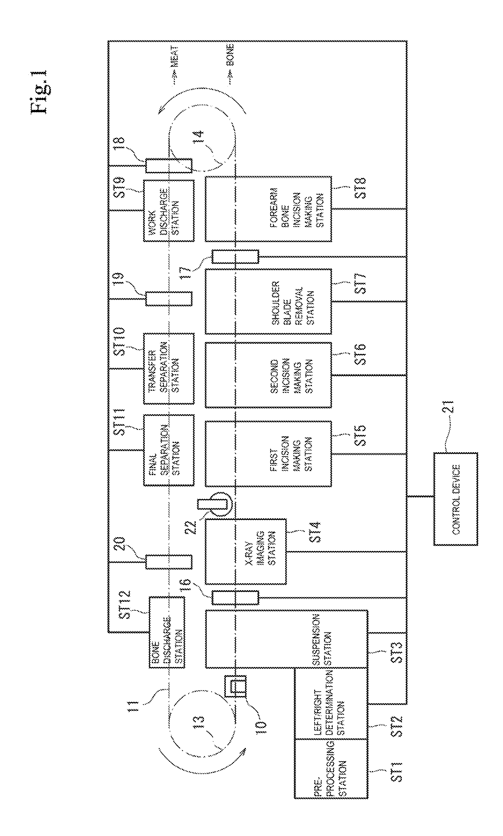
[0109]FIG. 1 shows the schematic configuration of a deboning system of bone-in meat (hereinafter also referred to as a deboning system) of an embodiment of the present invention.

[0110]The deboning system has a pre-processing station ST1, a left / right determination station ST2, a suspension station ST3, an X-ray imaging station ST4, a first incision making station ST5, a second incision making station ST6, a shoulder blade removal station ST7, a forearm-bone incision making station ST8, a work discharge station ST9, a transfer separation station ST10, a final separation station ST11, and a bone discharge station ST12.

[0111]...


PUM

PropertyMeasurementUnit
incident angleaaaaaaaaaa
lengthaaaaaaaaaa

Abstract

An X-ray image capturing device of bone-in meat for capturing an X-ray image of the bone-in meat that is from an arm part or a thigh part of a livestock carcass in a state where the bone-in meat is suspended, comprises: an X-ray source for irradiating the bone-in meat with an X-ray; a shielding box for covering the bone-in meat while the X-ray image is captured; a sensor which is disposed in the shielding box and which detects the X-ray which passes through the bone-in meat; and a filter which is disposed between the bone-in meat and the X-ray source and which adjusts an intensity distribution of the X-ray with which the bone-in meat is irradiated.

Description

CROSS-REFERENCE TO RELATED APPLICATIONS[0001]This application is a continuation of International Application No. PCT / JP2013 / 055299, filed on Feb. 28, 2013, and is based on and claims priority to Japanese Patent Application No. JP 2012-056286, filed on Mar. 13, 2012. The disclosure of the Japanese priority application and the PCT application in their entirety, including the drawings, claims, and the specification thereof, are incorporated herein by reference.BACKGROUND[0002]1. Field of the Invention[0003]The present invention relates to a device and a method for capturing x-ray image of bone-in meat from an arm part or a thigh part of a livestock carcass, and a deboning system of bone-in meat including the device.[0004]2. Discussion of the Background[0005]A carcass of livestock such as a pig, a cow, or a sheep is served as meat. A deboning method of bone-in meat (hereinafter referred to as a “work”) from an arm part or a thigh part of the livestock carcass roughly has a pre-processin...

Claims


Application Information

Patent Timeline
Patent Type & Authority Patents(United States)
IPC IPC(8): G01N23/04A22B5/00A22C17/00G21K1/00G01N33/12
CPCG01N23/04A22B5/007A22B5/0035A22C17/004A22C17/0086A22C17/0093G01N33/12G21K1/00G01N23/044
Inventor TANIGUCHI, AKIRASAKURAYAMA, HIROYUKIGOTO, OSAMUTOKUMOTO, MASARUMURANAMI, HIROAKI
Owner MAYEKAWA MFG CO LTD
Learn More