Eureka AIR delivers breakthrough ideas for toughest innovation challenges, trusted by R&D personnel around the world.

Method for the adjustment of a colour filter for a ditigial sensor and the associated filter

a ditigial sensor and colour filter technology, applied in the field of adaptive colour filters, can solve the problems of reducing the sensitivity of the associated digital sensor, filter quality is not suitable for providing sufficient quality, and the image quality is affected, so as to achieve the effect of adapting optical properties

Active Publication Date: 2016-12-13
SWISS TIMING
View PDF9 Cites 0 Cited by
  • Summary
  • Abstract
  • Description
  • Claims
  • Application Information

AI Technical Summary

Benefits of technology

[0010]It is an object of the present invention to provide a new type of colour filter which has adaptive optical properties, and a new, particularly practical method of adjusting a photo finish camera using such a filter.
[0017]An advantage of this invention is that it makes it possible to permanently optimise the optical properties of the colour photos obtained using the proposed filter, regardless of the conditions of use.
[0018]A further advantage of the proposed solution is that it allows for fast and efficient adjustment of the optical parameters chosen for the shot, and in particular, according to a preferred embodiment according to which all the adjustments are made by software, without requiring any movement of the photo finish camera in any of its degrees of freedom. Thus, fine adjustments for aligning the photo finish camera in relation to the finish line may be made once and for all, with the filter adjustments being obtained uniquely by software processing. Permanently locking all degrees of freedom and the absence of any physical handling of the photo finish camera considerably simplifies the adjustment operations whilst allowing for adaptation to the maximum possible types of race conditions.

Problems solved by technology

A drawback of this type of colour filter is the considerable reduction in sensitivity of the associated digital sensor due to the significant attenuation of light which reaches the sensor.
Nevertheless, these filters are not suited to provide sufficient quality in all race conditions.
Indeed, depending for example on the time of the competition or the weather conditions, the ambient luminosity may vary significantly and thereby strongly impair the quality of the images obtained.

Method used


Image

  • Method for the adjustment of a colour filter for a ditigial sensor and the associated filter
  • Method for the adjustment of a colour filter for a ditigial sensor and the associated filter
  • Method for the adjustment of a colour filter for a ditigial sensor and the associated filter

Examples


Embodiment Construction

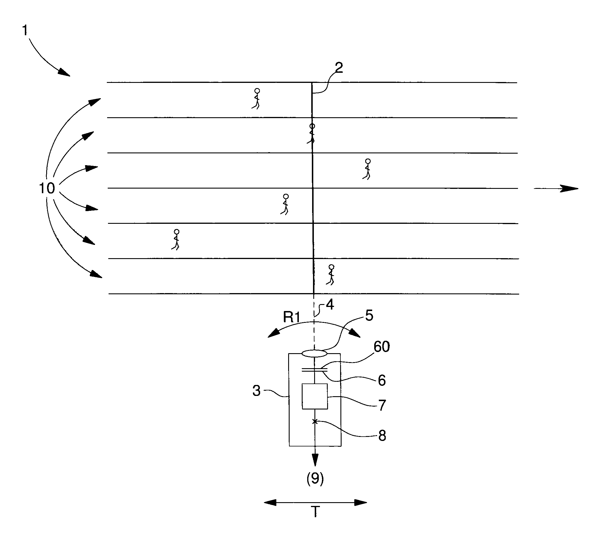
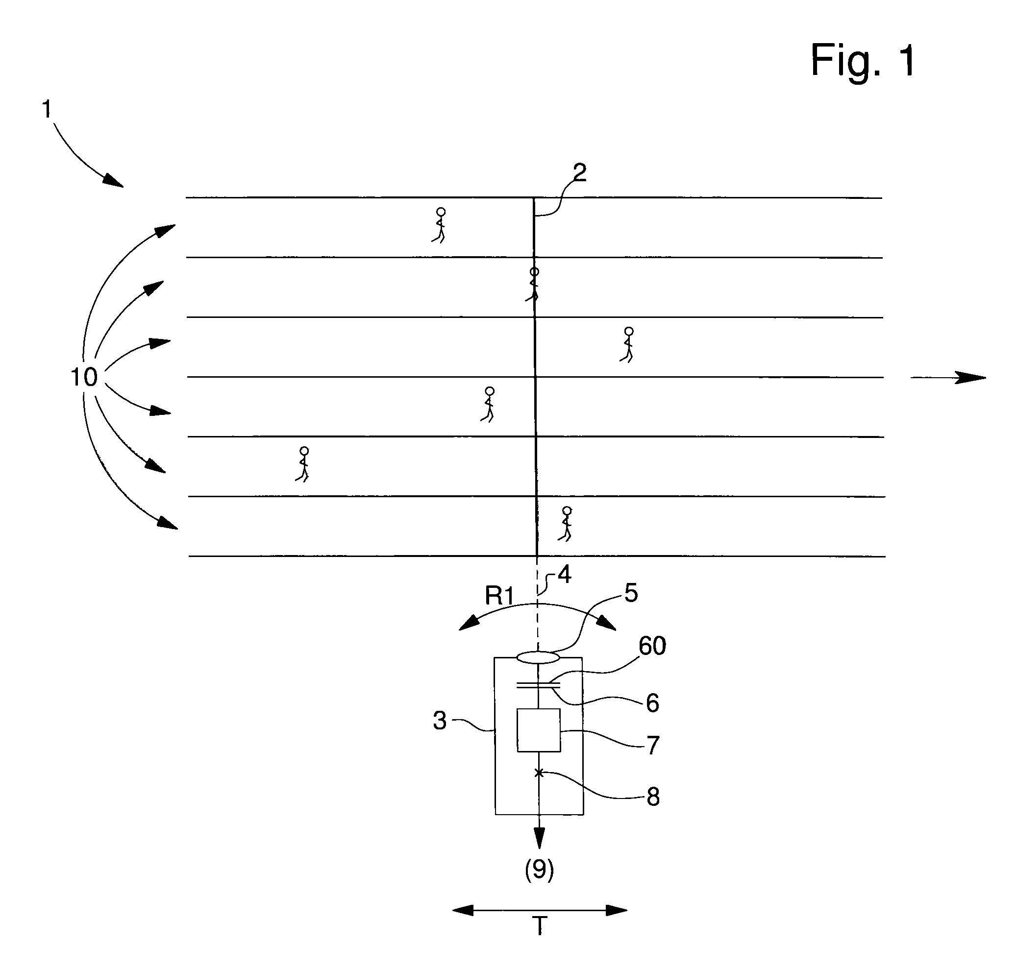
[0023]FIG. 1 shows a block diagram of a photo finish camera used according to this invention. The preferably LS-CDD photo finish camera 3, is aligned on the finish line 2 of a track 1 preferably including several lanes 10 in which different competitors move. It is to be noted that the example of an athletics track 1 is purely indicative and non-limiting, photo finish cameras 3 may also be used in cycling races, car track races, or also for horse races.

[0024]Photo finish camera 3 preferably has four degrees of freedom: three in rotation and one in translation. In FIG. 1 only the transverse degree of freedom T and the first rotational degree of freedom R1 about a vertical axis are shown. Nevertheless the camera is preferably rotatably mounted about a ball and socket joint 8 which simultaneously has second and third additional rotational degrees of freedom R2, R3 in order to manage the alignment of the optical axis 4 of camera 3 on finish line 2. Photo finish camera 3 includes a digita...


PUM


Abstract

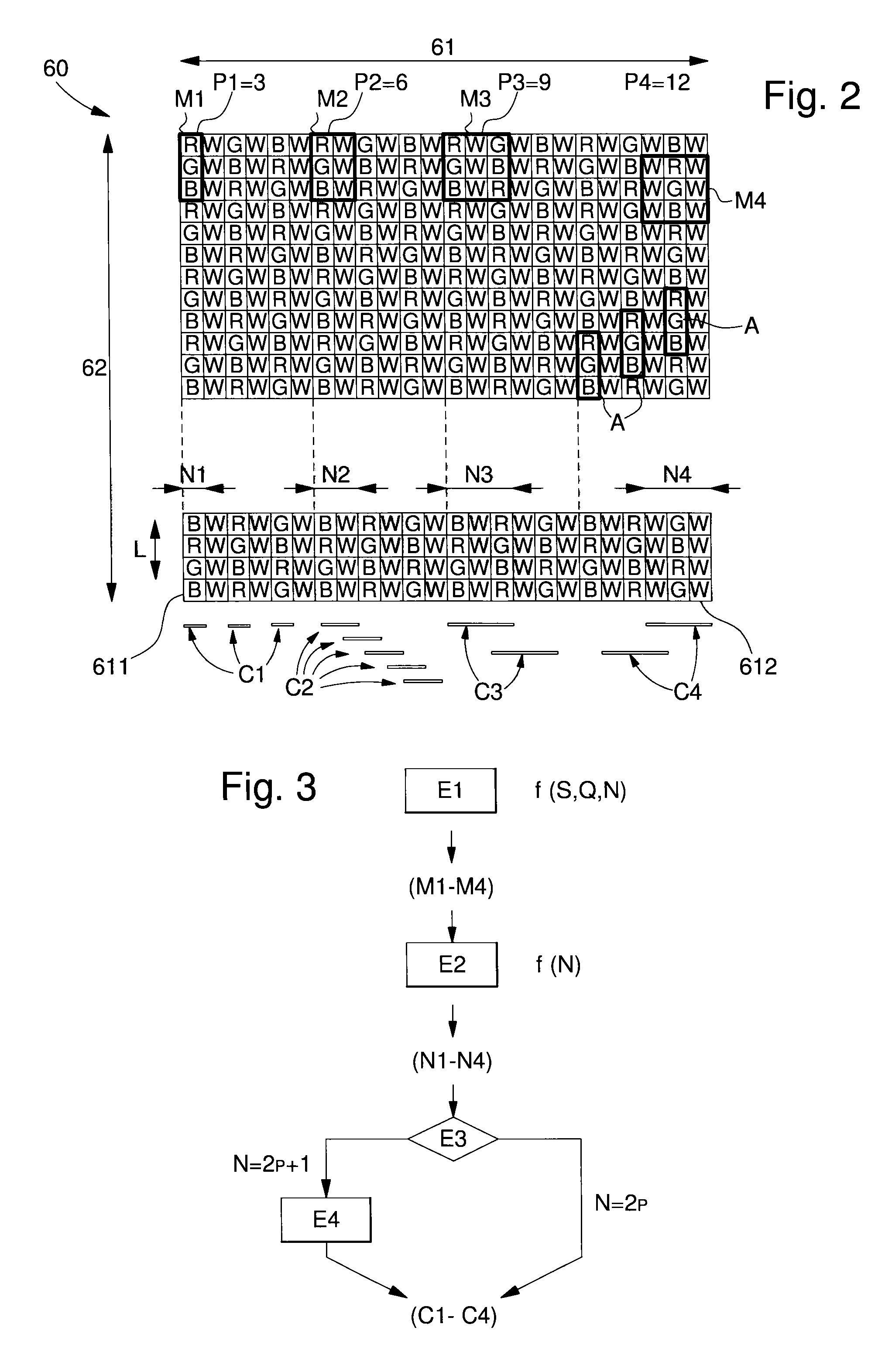
Method for the adjustment of a photo finish camera including a matrix color filter, characterized in that the method includes the following steps:a first step of selecting a basic pattern having optical properties of sensitivity, of color quality and of resolution which are predefined according to race parameters;a second step of software selection of a set of adjacent columns whose number corresponds to the width of said selected basic pattern;a third step of centering said set of adjacent columns on the finish line.

Description

[0001]This application claims priority from European Patent Application No. 13199041.8 filed on 20 Dec. 2013, the entire disclosure of which is hereby incorporated herein by reference.FIELD OF THE INVENTION[0002]The present invention concerns an adaptive colour filter including columns of coloured pixels and columns of white pixels for a digital array sensor, and a method of parameterization for such a filter for use in a photo finish camera.STATE OF THE ART[0003]Photosensitive sensors, formed of a mosaic of pixels, have long been known in the field of digital photography; the sensors most widely used for digital cameras use, for example, CCD (charge-coupled device) or CMOS (complementary metal oxide semiconductor) technology. In order to produce colour images, colour filters are applied to these digital sensors; the filters also take the form of an array of different colours, each colour being dedicated to a pixel of the sensor on which it is superposed. The colour that must be ass...

Claims


Application Information

Patent Timeline
Patent Type & Authority Patents(United States)
IPC IPC(8): H04N9/04H04N5/369G02B5/20
CPCH04N9/045G02B5/201H04N5/3692H04N25/701H04N25/133H04N25/135
Inventor RICHARD, PASCALBLONDEAU, FABIENMUELLER, JENS HERMANNGRESS, OLIVER
Owner SWISS TIMING
Why Eureka
Eureka Blog
Learn More