Device and method for determining at least one objective eye refraction parameter of a subject depending on a plurality of gaze directions
a technology of objective eye refraction and device, which is applied in the field of optometric devices and methods, can solve the problems of difficult (or even impossible in certain cases) to align the measuring channel with the natural gaze axis of the subject, the optometric apparatus of autorefractor or aberrometer type, etc., and achieve the effect of improving the precision of ophthalmological measurements and improving the differentiation of correction
Active Publication Date: 2016-12-20
ESSILOR INT CIE GEN DOPTIQUE
View PDF12 Cites 1 Cited by
- Summary
- Abstract
- Description
- Claims
- Application Information
AI Technical Summary
Benefits of technology
[0011]The invention aims to provide an optometric device for measuring at least one vision parameter for various set vision distances and for various set vision directions. In particular, the invention aims to provide an optometric device allowing measurements to be carried out at distances and along directions that follow the natural gaze declination of the subject.
[0012]The invention also aims to provide a precise measurement of the variation in vision parameters as a function of the declination of the gaze, using objective measuring means, i.e. not requiring subjective measuring means that are complex and time-consuming to implement (for example implementing a test lens or a refractor).
Problems solved by technology
Progressive or multifocal lenses are not only able to correct an optical power error but also other visual defects, in particular astigmatism.
However, if it is desired to use an apparatus that is currently commercially available in a natural lowered or raised gaze direction, it is technically difficult (or even impossible in certain cases) to align the measuring channel with the natural gaze axis of the subject.
Currently, there is no autorefractor or aberrometer type optometric apparatus that allows the far-vision / near-vision differentiated refraction effect to be studied while the gaze is naturally lowered.
Method used
View moreImage
Smart ImageViewing Examples
Examples
first embodiment
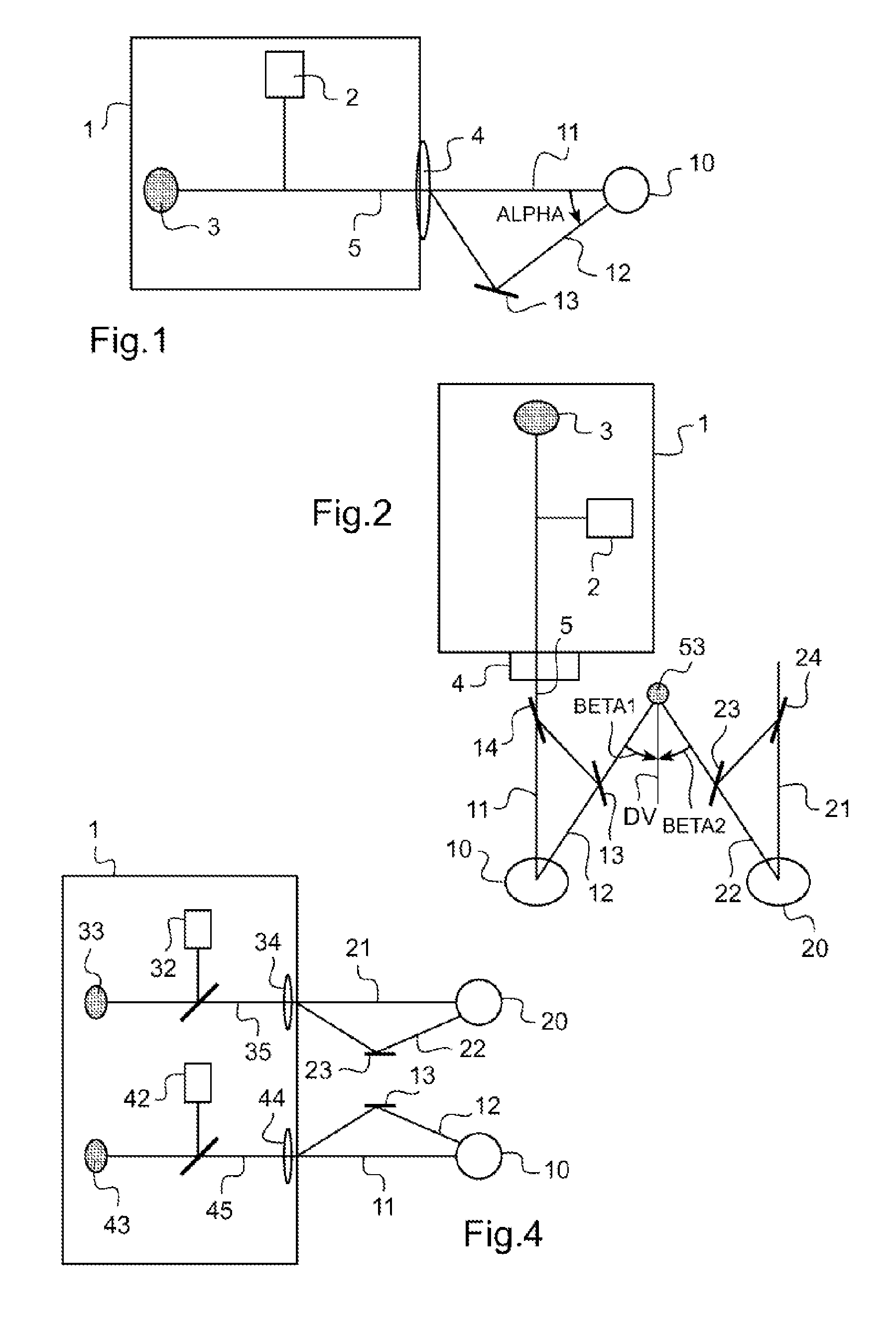
[0042]FIG. 1 schematically shows a monocular device according to the invention;
second embodiment
[0043]FIG. 2 shows a top view of a binocular FV / NV differentiated optometric device according to the invention;
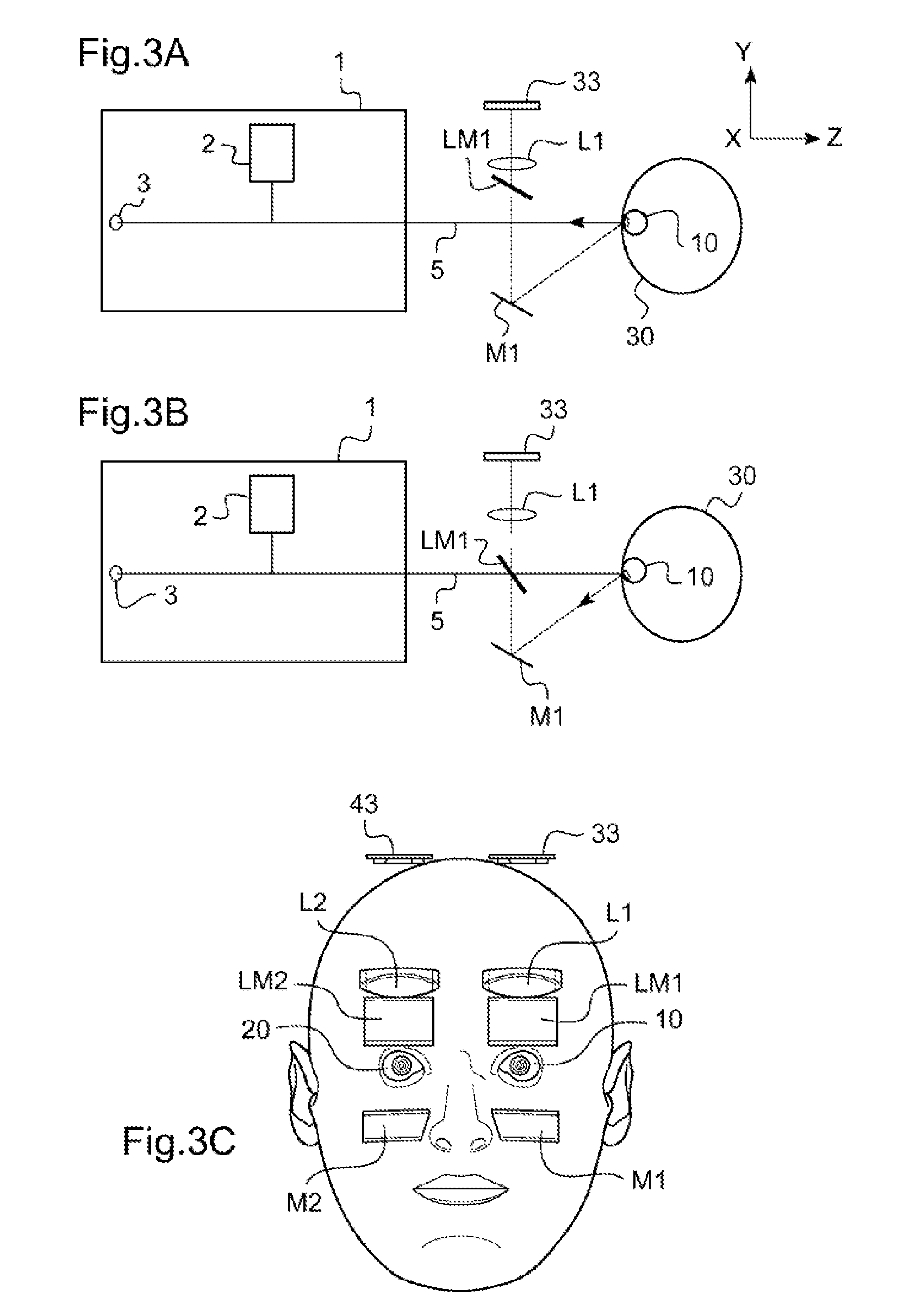
[0044]FIGS. 3A-3E schematically show an accessory for a monocular or binocular device according to one preferred embodiment of the invention;
third embodiment
[0045]FIG. 4 schematically shows a binocular device according to the invention;
Login to View More PUM
 Abstract
Device and method for determining an objective eye refraction parameter of a subject depending on a plurality of gaze directions, the device includes elements for ophthalmologically measuring an objective eye refraction parameter of a subject, and elements of visual stimulation of variable proximity and intended to stimulate the visual accommodation of the subject for first and second proximity values. The device includes opto-mechanical alignment elements for carrying out a first optical alignment of the optical axis of measurement on an eye axis in a first measuring position corresponding to a first angle of lowered viewing associated with a first proximity value to take a first measurement of an objective eye refraction parameter of the subject, and a second alignment of the optical axis of measurement on the eye axis in another measuring position corresponding to another angle of lowered viewing associated with another proximity value to take a second measurement.
Description
TECHNICAL FIELD OF THE INVENTION[0001]Generally, the present invention relates to the field of optometric devices and methods. More particularly, the invention relates to an optometric apparatus for determining the various values of the prescription of a lens for a pair of spectacles for progressive or multifocal visual correction, or for a pair of spectacles intended for near-vision correction (reading glasses), which values are associated with measurement of ocular refraction differentiated between a plurality of gazes and in particular a far-vision gaze and a near-vision gaze. These measurements are intended to be used for the optical design and the manufacture of the refracting faces of corrective progressive or multifocal lenses for pairs of spectacles, or for pairs of spectacles intended to correct near vision (non-prescription, reading glasses), whether it is a question of passive lenses or lenses having electronically controlled variable optical powers.PRIOR ART[0002]Over th...
Claims
Login to View More Application Information
Patent Timeline
 Patent Type & Authority Patents(United States)
IPC IPC(8): A61B3/103A61B3/15A61B3/107A61B3/00A61B3/18G02C7/02
CPCA61B3/103A61B3/0075A61B3/0091A61B3/107A61B3/1035A61B3/152A61B3/0083A61B3/18G02C7/025
Inventor BARANTON, KONOGANDIVO, FABIENESCALIER, GUILHEMHERNANDEZ-CASTANEDA, MARTHAMARIN, GILDASOURIVES, PEDROROUSSEAU, BENJAMIN
Owner ESSILOR INT CIE GEN DOPTIQUE
Features
- R&D
- Intellectual Property
- Life Sciences
- Materials
- Tech Scout
- Unparalleled Data Quality
- Higher Quality Content
- 60% Fewer Hallucinations
Learn More Browse by: Latest US Patents, China's latest patents, Technical Efficacy Thesaurus, Application Domain, Technology Topic, Popular Technical Reports.
© 2025 PatSnap. All rights reserved.Legal|Privacy policy|Modern Slavery Act Transparency Statement|Sitemap|About US| Contact US: help@patsnap.com


