Polymeric coil assembly and method of making the same

a polymer coil and coil assembly technology, applied in the field of coil assembly, can solve the problems of circulating water, only having a gallvanizing coating on the outside of the tube, and quickly deteriorating the inside of the steel tubing

Active Publication Date: 2016-12-20
BRENTWOOD INDS
View PDF25 Cites 2 Cited by
  • Summary
  • Abstract
  • Description
  • Claims
  • Application Information

AI Technical Summary

Problems solved by technology

However, the galvanizing coating is only on the outside of the tubes.
Therefore, circulating water from an open system which is continually aerated will quickly deteriorate the inside of the steel tubing.
For this reason, much more expensive stainless steel tubing coils are required for fluid coolers operating in an open system.
The polymeric coils of PowerCold Corporation included a serpentine coil assembly made by folding an elongated bundle of polymeric tubes, but there were issues regarding the heat transfer through the bundle, especially at the return bends.

Method used


Image

  • Polymeric coil assembly and method of making the same
  • Polymeric coil assembly and method of making the same
  • Polymeric coil assembly and method of making the same

Examples


Embodiment Construction

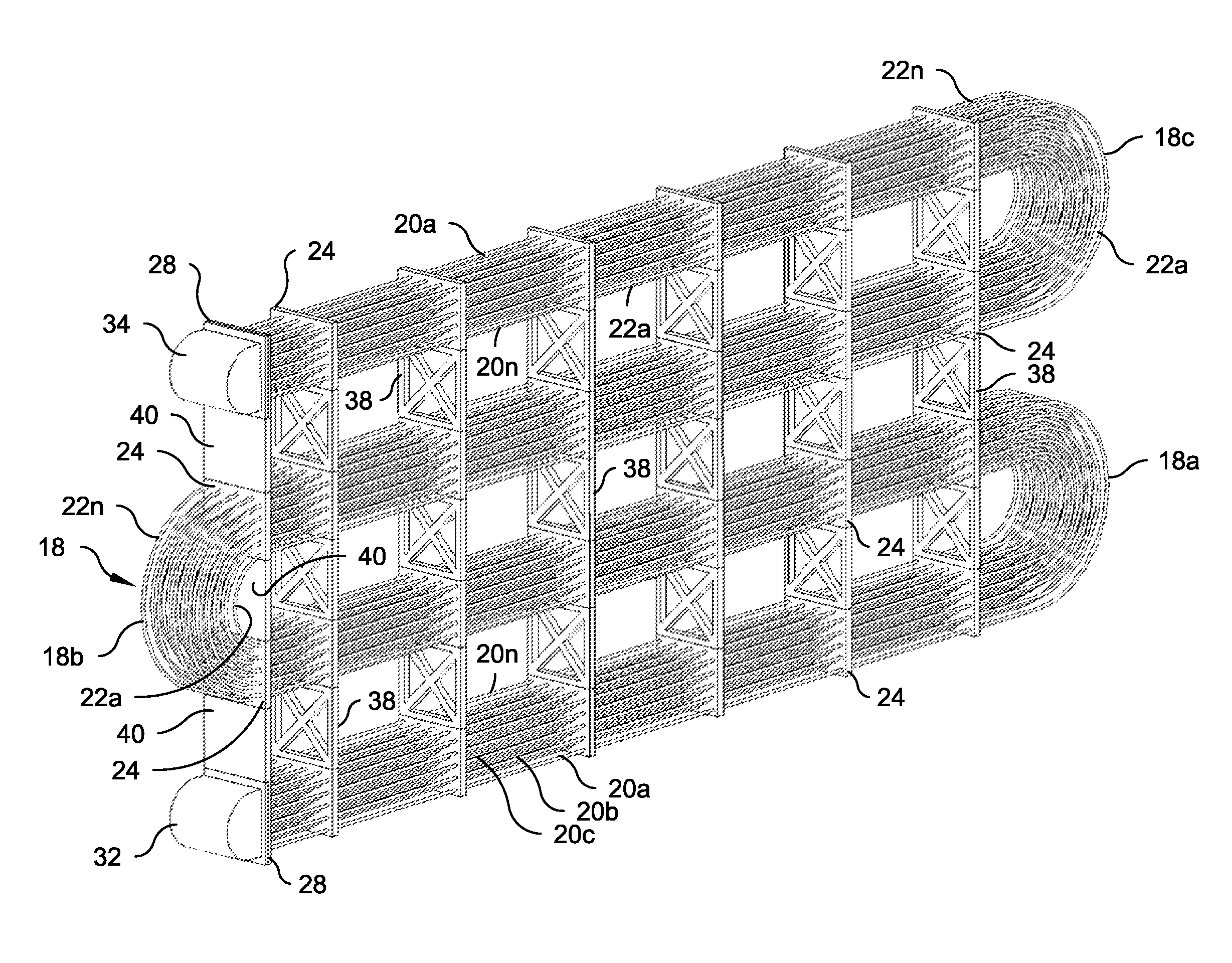
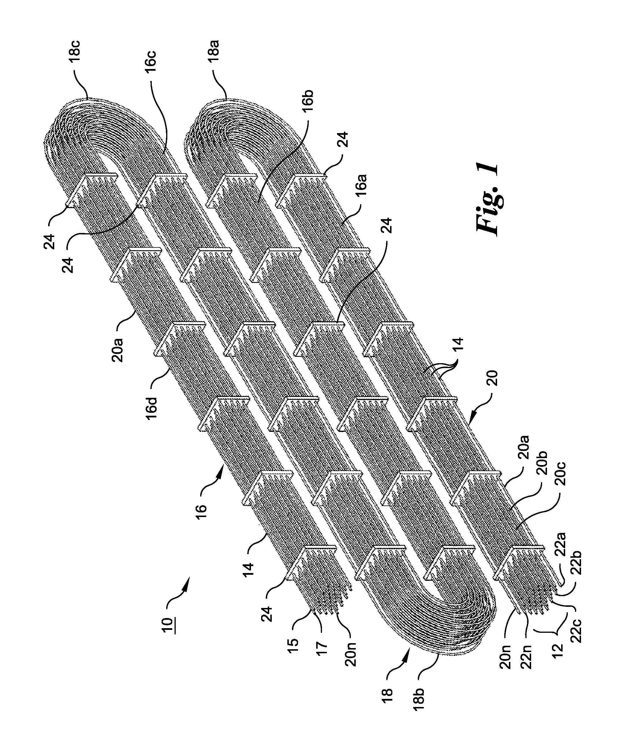
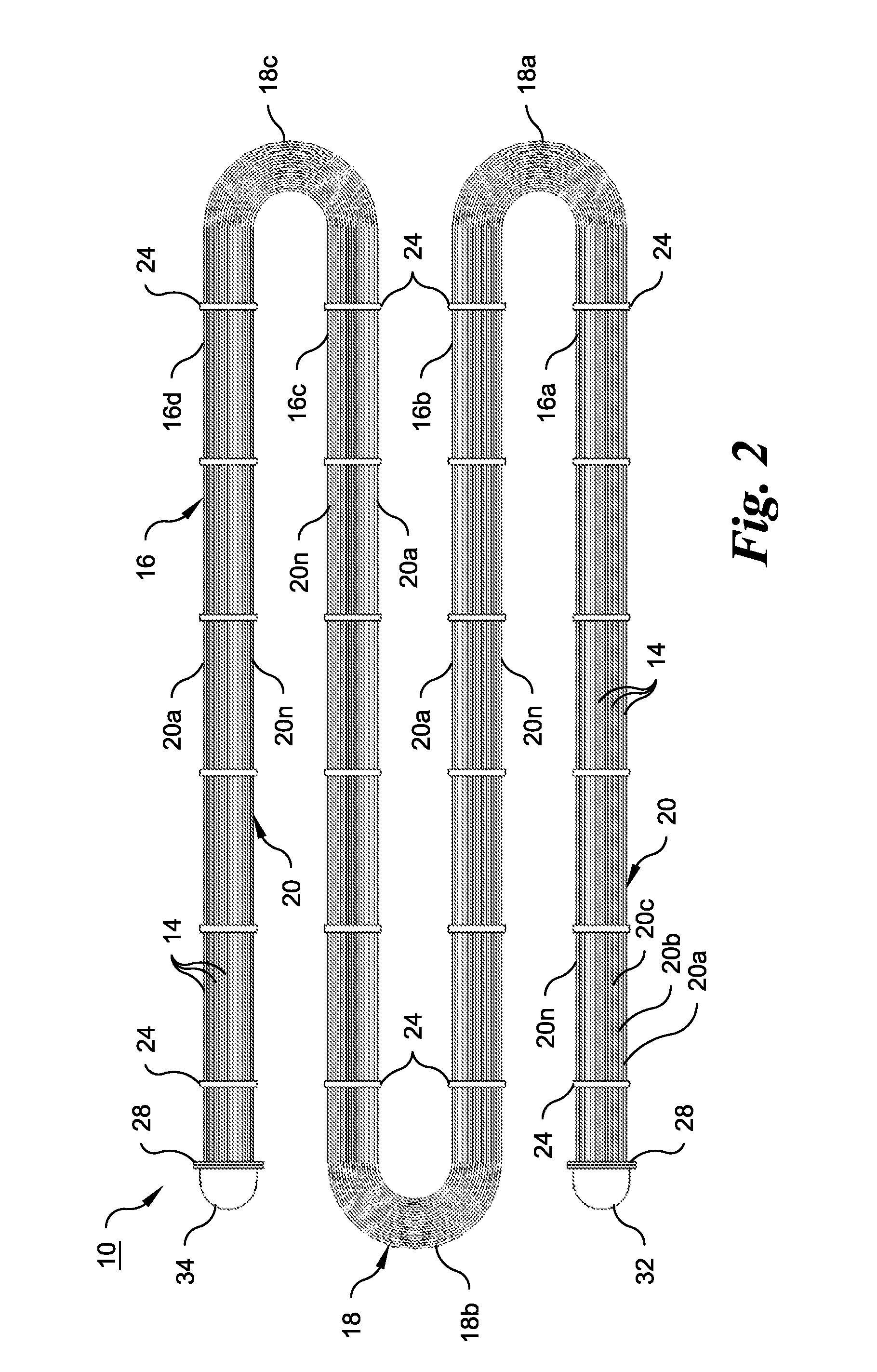
[0058]With reference initially to FIGS. 1 and 2, one embodiment according to an aspect of the present invention is illustrated as a coil assembly 10 that comprises an array 12 of polymeric tubes 14 arranged along a pathway including at least two generally linear passes 16, such as the lowest pass 16a, intermediate passes 16b and 16c, and a top pass 16d. Any number of passes 16 may be used in the coil assembly 10, as determined by space within the heat exchange apparatus in which the coil assembly 10 is used and the heat transfer capacity required for any of a great many types of heat exchange purposes of any given nature. The passes extend for a predetermined longitudinal distance determined by space limitations in the heat exchange apparatus. The array 12 of tubes 14 extends between the passes 16 by way of one return bend 18 between each two passes 16. In other words, the return bends 18 connect the passes 16, such as the return bend 18a connects the passes 16a and 16b, the return ...


PUM

PropertyMeasurementUnit
lengthaaaaaaaaaa
lengthaaaaaaaaaa
pressureaaaaaaaaaa

Abstract

Coil assemblies for use in heat exchange applications are made using polymeric tubes, some with heat exchange and water redistribution media integral with the coil assembly and others with a water distribution subassembly integral with the coil assembly. One coil assembly includes at least two generally linear passes that are connected by return bends formed by folding an array of polymeric tubes. The passes have an array of at least two layers of polymeric tubes that pass through alignment holes in tube spacers only along the passes to maintain the tubes in substantially the same relative positional relationship to each other in the passes and in the return bends. Methods are explained for forming the coil assemblies and components, including the tube spacers and tube sheets to connect the coil assembly to inlet and outlet manifolds for the processing fluid flowing internally through the tubes.

Description

CROSS-REFERENCE TO RELATED APPLICATIONS[0001]This application is an application under 35 U.S.C. §371 of International Application No. PCT / US2014 / 033086, filed Apr. 4, 2014, which was published in the English language on Oct. 9, 2014, under International Publication No. WO 2014 / 165826 A1, and also claims the benefit of U.S. Provisional Patent Application No. 61 / 808,608, filed Apr. 4, 2013, and U.S. Provisional Patent Application No. 61 / 819,743, filed May 6, 2013. The disclosures in their entirety of the International application and the U.S. Provisional Patent Applications are hereby incorporated herein by reference.STATEMENT REGARDING FEDERALLY SPONSORED RESEARCH OR DEVELOPMENT[0002]Not applicable.REFERENCE TO A MICROFICHE APPENDIX[0003]Not applicable.BACKGROUND OF THE INVENTION[0004]The present invention relates to a coil assembly including tubes made of synthetic polymeric material, rather than metal, such as galvanized steel or stainless steel, referred to hereinafter generally a...

Claims


Application Information

Patent Timeline
Patent Type & Authority Patents(United States)
IPC IPC(8): B23P15/26F28F21/06F28F9/16F28D1/047F28F9/013B29C45/14
CPCF28F9/0131B23P15/26B29C45/14614F28D1/0477F28F9/013F28F9/16F28F9/162F28F21/06F28F21/062F28F21/067
Inventor KRELL, TIMOTHY E.KULICK, III, FRANK M.CALTON, DEAN
Owner BRENTWOOD INDS
Why Eureka
Try Eureka