Shell-and-tube heat exchanger with un-notched traverse baffles

A technology of shell-and-tube heat exchangers and baffles, which is applied in the direction of indirect heat exchangers, heat exchanger types, heat exchanger shells, etc., to improve heat exchange efficiency, reduce heat transfer "dead zones, and reduce The effect of pressure drop

Active Publication Date: 2013-01-02
BEIJING UNIV OF CHEM TECH
View PDF1 Cites 0 Cited by
  • Summary
  • Abstract
  • Description
  • Claims
  • Application Information

AI Technical Summary

Problems solved by technology

[0003] The purpose of the present invention is to solve the technical problems existing in the current common arcuate baffle heat exchanger, and to provide a shell-and-tube heat exchanger with no notch baffles, which passes the fluid in the shell side of the ordinary arcuate baffle heat exchanger through the The cross flow through the tube bundle is changed to the flow along the tube bundle to reduce the pressure drop, reduce the heat transfer "dead zone", improve the heat transfer efficiency, and slow down the vibration and wear of the tubes

Method used


Image

  • Shell-and-tube heat exchanger with un-notched traverse baffles
  • Shell-and-tube heat exchanger with un-notched traverse baffles
  • Shell-and-tube heat exchanger with un-notched traverse baffles

Examples


Embodiment 1

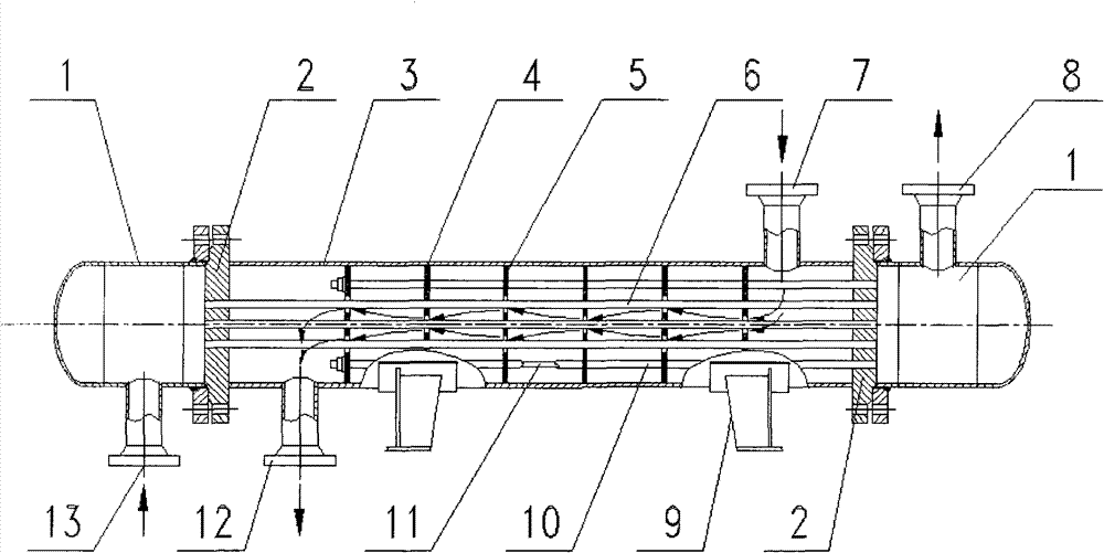
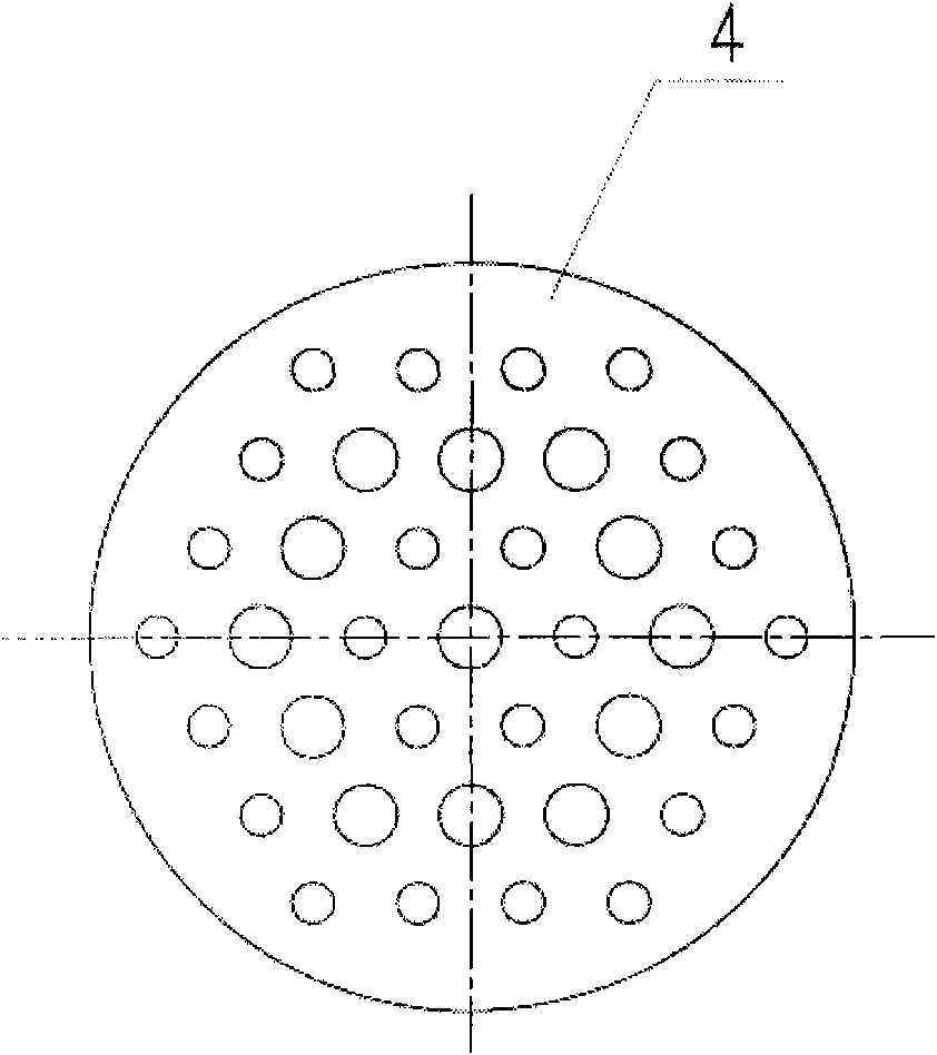
[0026]The shell-and-tube heat exchanger with no gap baffles of the present invention can be found in figure 1 , including: a cylinder 3 placed on the saddle 9, shell-side fluid inlet 7 and shell-side fluid outlet 12 are respectively opened on both ends of the cylinder, fixed tube sheets 2 are arranged at both ends of the cylinder, and the outer sides of the two tube sheets are respectively Two tube boxes 1 are connected, and the two tube boxes are respectively opened with a tube-side fluid inlet 13 and an outlet 8. There is a heat exchange tube bundle 6 in the cylinder, and the tube bundle passes through a set of tube holes of baffles 4 and 5 without gaps. Parallel fixed between the tube plates, the baffles are uniformly fixed in the axial direction by the tie rods 11 and the spacer tubes 10 . The distribution of the tube holes on the baffle is triangular. The tube-side fluid of the heat exchange medium is water, and the inlet temperature is 20°C. The shell-side fluid is C6 oi...

Embodiment 3

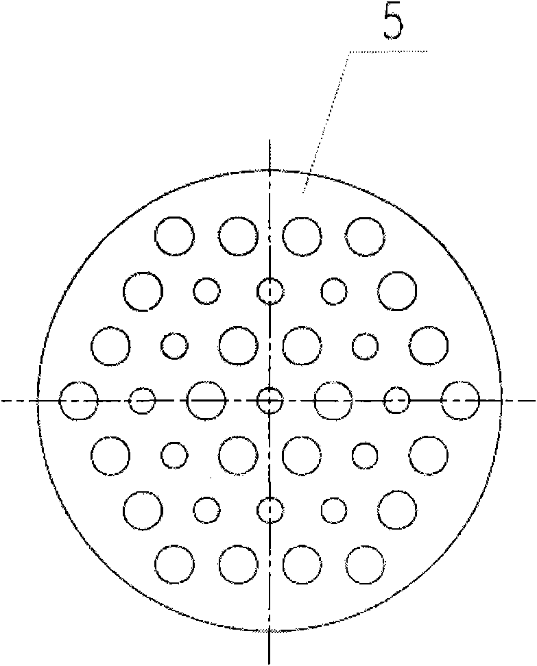
[0034] For the non-notched baffle shell and tube heat exchanger of the present invention, refer to Figure 7 , including: a cylinder body 5 placed on the saddle 10, shell side fluid inlet 4 and shell side fluid outlet 9 respectively opened at both ends of the cylinder body 5, one end of the cylinder body 5 is connected to the fixed tube sheet 3 through a flange, and the tube sheet The outer side is connected to the tube box 1 (left tube box). The tube box 1 is respectively provided with a tube-side fluid inlet 13 and an outlet 2. There are U-shaped tube bundles 8 and baffles 6 and 7 in the cylinder body 5. The baffles are perpendicular to the tubes. The shaft is fixed parallel and evenly distributed along the axial direction by the tie rod 12 and the spacer tube 11. The tie rod 12 is fixed on the tube plate 3, and the baffles 6 and 7 are non-notch baffles, and each baffle has different sizes. Two kinds of circular tube holes, the distribution of the circular tube holes of any ...


PUM


Abstract

A shell and tube heat exchanger comprises a cylinder (3) with a shell side fluid inlet (7) and a shell side fluid outlet (12) thereon and a tube box (1) with a tube side fluid inlet (13) and a tube side fluid outlet (8) thereon. The cylinder (3) is connected to the tube box (1) through fixed tube sheets (2) at two ends of the cylinder (3). Heat exchange tube bundle (6) and baffle plates (4) perpendicular to the axis of the tubes are arranged in the cylinder (3). The baffle plates (4) are fixed in parallel along the axis and uniformly distributed by a draw rod (11) and a tube spacer (10). The draw rod (11) is fixed on the tube sheets (2). Two kinds of circular tube holes, in which one is large and another is small, are arranged on the baffle plate (4) according to the conventional technique. The arrangements of large and small circular tube holes on the adjacent baffle plates (4) are different from each other. The tube bundle (6) passes through the tube holes of a group of baffle plates (4) and is fixed between the tube sheets (5) in parallel with the axis. The baffle plate (4) can be applied in a floating head and a U-shaped tube heat exchanger. The shell and tube heat exchanger has the advantages of reducing the pressure fall and the dead area of heat transfer, increasing the heat transfer efficiency and alleviating the vibration and abrasion of the tube.

Description

technical field [0001] The invention relates to a shell-and-tube heat exchanger, in particular to a shell-and-tube heat exchanger with no-notch baffles. Due to the use of no-notch baffles, the fluid in the shell side of an ordinary arcuate baffle heat exchanger is Change from cross flow through the tube bundle to flow along the tube bundle. Background technique [0002] Shell and tube heat exchangers have the advantages of high reliability, adaptability, design, manufacture and simple use, and are widely used in petrochemical, electric power, environmental protection and other industrial fields. Shell and tube heat exchangers are usually composed of tube boxes, tube sheets, shells, baffles, heat exchange tubes, tie rods, distance tubes, and process connections. Among them, in addition to supporting the tube bundle in the horizontal heat exchanger shell, the baffle also plays a role in making the fluid flow in a specific channel, increasing the flow velocity of the shell-sid...

Claims


Application Information

Patent Timeline
Patent Type & Authority Patents(China)
IPC IPC(8): F28F9/24
CPCF28D7/16F28F9/22
Inventor 钱才富
Owner BEIJING UNIV OF CHEM TECH
Why Eureka
Try Eureka