Spark plug

a technology of spark plugs and annular portions, applied in spark plugs, basic electric elements, electric devices, etc., can solve the problems of inability to generate spark discharge, and achieve the effect of enhancing the effect of preventing separation and cracking of the tip and reducing the stress between the tip and the annular portion

Active Publication Date: 2016-12-20
NGK SPARK PLUG CO LTD
View PDF6 Cites 0 Cited by
  • Summary
  • Abstract
  • Description
  • Claims
  • Application Information

AI Technical Summary

Benefits of technology

[0029]In view of this point, according to the above-described configuration 5, the tip is joined to the annular portion in a centrally located sub-region among three sub-regions obtained by equally trisecting the region between the adjacent recesses along the circumferential direction. Namely, the tip is joined to a portion of the annular portion where its deformation along the circumferential direction is particularly small. Accordingly, the difference in stress occurring between the tip and the annular portion can be decreased very effectively. As a result, the effect of preventing separation and cracking of the tip can be enhanced further.

Problems solved by technology

When the discharge voltage becomes excessively large, generation of spark discharge becomes impossible (so-called misfire occurs).

Method used


Image

  • Spark plug
  • Spark plug
  • Spark plug

Examples


Embodiment Construction

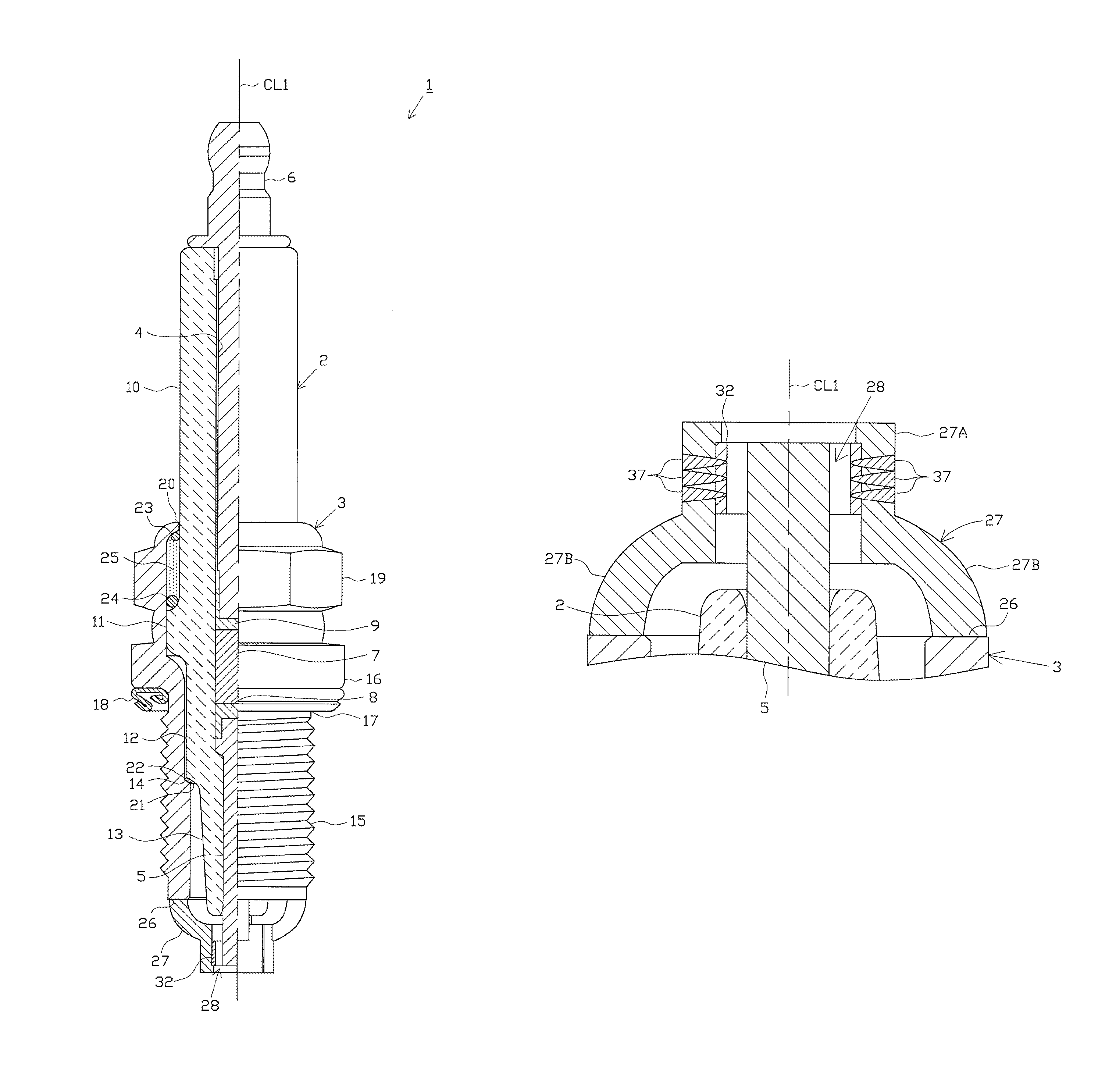
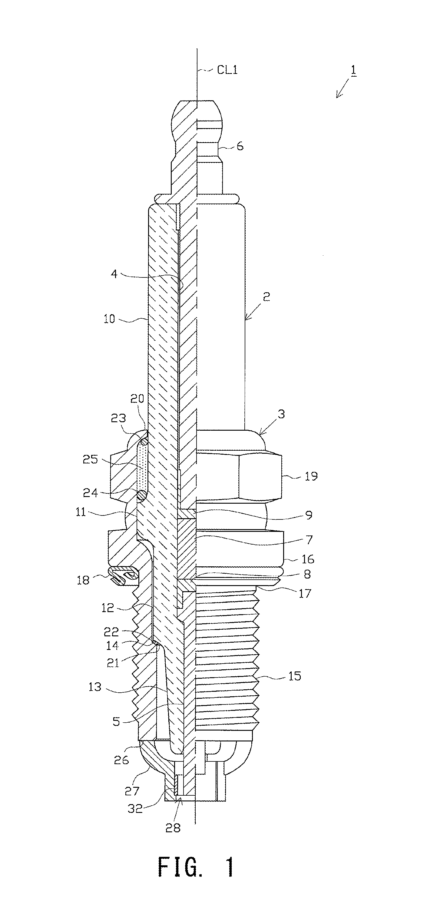
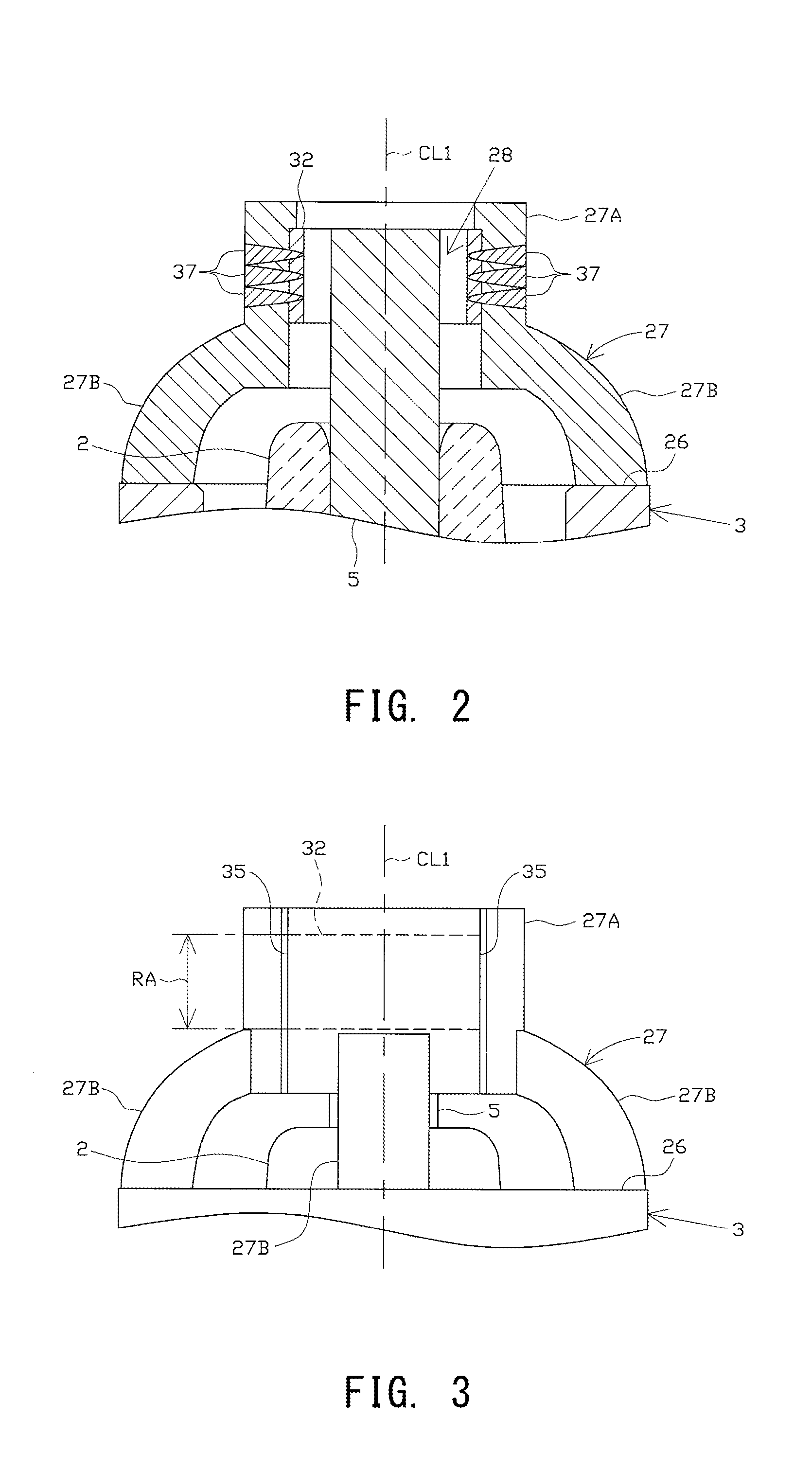
[0055]One embodiment will now be described with reference to the drawings. FIG. 1 is a partially cutaway front view showing a spark plug 1. In FIG. 1, the direction of an axial line CL1 of the spark plug 1 is referred to as the vertical direction. In the following description, the lower side of the spark plug 1 in FIG. 1 is referred to as the forward end side of the spark plug 1, and the upper side as the rear end side.

[0056]The spark plug 1 includes a tubular ceramic insulator 2, which corresponds to the insulator in the present invention, and a tubular metallic shell 3, which holds the ceramic insulator 2 therein.

[0057]The ceramic insulator 2 is formed from alumina or the like by firing, as well known in the art. The ceramic insulator 2, as viewed externally, includes a rear trunk portion 10 formed at its rear end side; a large-diameter portion 11 located forward of the rear trunk portion 10 and protruding radially outward; an intermediate trunk portion 12 located forward of the l...


PUM


Abstract

A spark plug (1) includes an insulator (2) having an axial hole (4), a center electrode (5) inserted into the axial hole (4), a metallic shell (3) provided around the insulator (2), a ground electrode (27) whose base end portion is fixed to the metallic shell (3) and which has an annular portion (27A) formed at a forward end portion thereof, the center electrode (5) being disposed radially inward of the annular portion (27A), and an annular tip (32) which is joined to the inner circumference of the annular portion (27A) and which forms a spark discharge gap (28) between the center electrode (5) and the inner circumferential surface of the annular tip (32). Recesses (35) are provided on at least one of the inner and outer circumferences of the annular portion (27A).

Description

CROSS REFERENCE TO RELATED APPLICATIONS[0001]This is a National Stage of International Application No. PCT / JP2014 / 001246 filed Mar. 6, 2014, claiming priority based on Japanese Patent Application No. 2013-122294 filed Jun. 11, 2013, the contents of all of which are incorporated herein by reference in their entirety.TECHNICAL FIELD[0002]The present invention relates to a spark plug for use in an internal combustion engine or the like.BACKGROUND ART[0003]A spark plug is attached to an internal combustion engine (engine) or the like, and is used to ignite, for example, a fuel-air mixture within a combustion chamber. In general, such a spark plug includes an insulator having an axial hole extending in the axial direction; a center electrode inserted into a forward end portion of the axial hole; a metallic shell provided around the insulator; and a ground electrode fixed to a forward end portion of the metallic shell. A high voltage is applied to a gap formed between a distal end portion...

Claims


Application Information

Patent Timeline
Patent Type & Authority Patents(United States)
IPC IPC(8): H01T13/20H01T13/32H01T13/39H01T13/54
CPCH01T13/32H01T13/39H01T13/54H01T13/16H01T13/467
Inventor MATSUNAGA, YUICHISAKAKURA, YASUSHI
Owner NGK SPARK PLUG CO LTD
Why Eureka
Try Eureka