Rib spreader

a rib and sternum technology, applied in the field of rib spreaders, can solve the problems of unnatural deformation of sternum, patient discomfort, and anticipated risk of sternum fracture, and achieve the effects of avoiding sternum fracture or crushing of sternum stumps, avoiding difference in stress, and preventing sternum from unnatural deformation during displacemen

Active Publication Date: 2015-03-17
MEDICAL PINE
View PDF18 Cites 0 Cited by
  • Summary
  • Abstract
  • Description
  • Claims
  • Application Information

AI Technical Summary

Benefits of technology

[0025]According to the present invention, by virtue of the rack which is bent archwise, the sternum may be prevented from unnaturally deformed during displacement. Additionally according to the present invention, the incision planes of sternum and the contact surfaces of the individual hooks may be kept in surface contact conforming to changes in the angle of incision planes of sternum, thereby difference in stress between the portions distant from the human body and closer to the human body may be reduced. As a consequence, fracture of sternum or crush of sternum stump are avoidable.
[0026]The individual embodiments of the present invention give effects as follows. By configuring the individual hook so as to be independently pivotable about the individual arms, the difference in stress between the portions of the individual contact surfaces on the superior thoracic aperture side and the inferior thoracic aperture side may be reduced. By configuring the intermediate hooks of the individual arms so as to be slidable, position of the hooks are adjustable in situ depending on the length of sternum of the patient, and a state of deformation of sternum during displacement. By configuring the stationary arm and the movable arm without forming on the surfaces thereof any projection such as nut, accidental hooking of surgical suture is avoidable. By using the rack curved archwise along a conical surface having a predetermined conical angle, or by using the rack curved archwise along the cylindrical surface together with the arm having a base end bent portion, the upper portion of heart may be more readily recognizable. As a consequence, personal differences such as the length of sternum of the patient, or the state of deformation of sternum during displacement may be absorbed, and thereby a good field of view and a sufficient working area for surgery, and a good operability and flexibility of adoption may be ensured.
[0027]Moreover, by configuring each of the stationary arm and the movable arm to have the intermediate bent portion and the front end bent portion, different changes in the angle of sternum between the portions thereof on the superior thoracic aperture side and the inferior thoracic aperture side may be absorbed, thereby both of the contact surfaces of the front end hooks brought into contact with the superior thoracic aperture side, and the contact surfaces of the intermediate hooks brought into contact with the inferior thoracic aperture side, may keep the state of surface contact with the incision planes of sternum. In other words, the unnatural deformation which may otherwise be anticipated in the process of displacement by which the sternum is displaced concomitantly on the superior thoracic aperture side and the inferior thoracic aperture side thereof, is avoidable. At the same time, difference in stress exerted on the contact surfaces between the portions distant from the human body and closer to the human body may be reduced. Accordingly, similarly as described in the above, fracture of sternum and crush of sternum stump are avoidable.

Problems solved by technology

The median sternotomy has, however, been anticipated for a risk of sternum fracture, particularly high in children, in the process of displacement by the rib spreader.
However, as the distance of spreading of sternum increases, the sternum will deform unnaturally as illustrated in FIG. 9, due to generation of component of force in the direction which acts to bring the sternum apart from the vertebral column (thoracic vertebra), even enough to detach the rib spreader during the displacement in some cases.
Such unnatural deformation and concentration of pressure may cause fracture of sternum or crush of sternum stump as a consequence, and the patient may feel unpleasant after surgery due to an excessive spreading of the ribs.

Method used


Image

  • Rib spreader
  • Rib spreader
  • Rib spreader

Examples


first embodiment

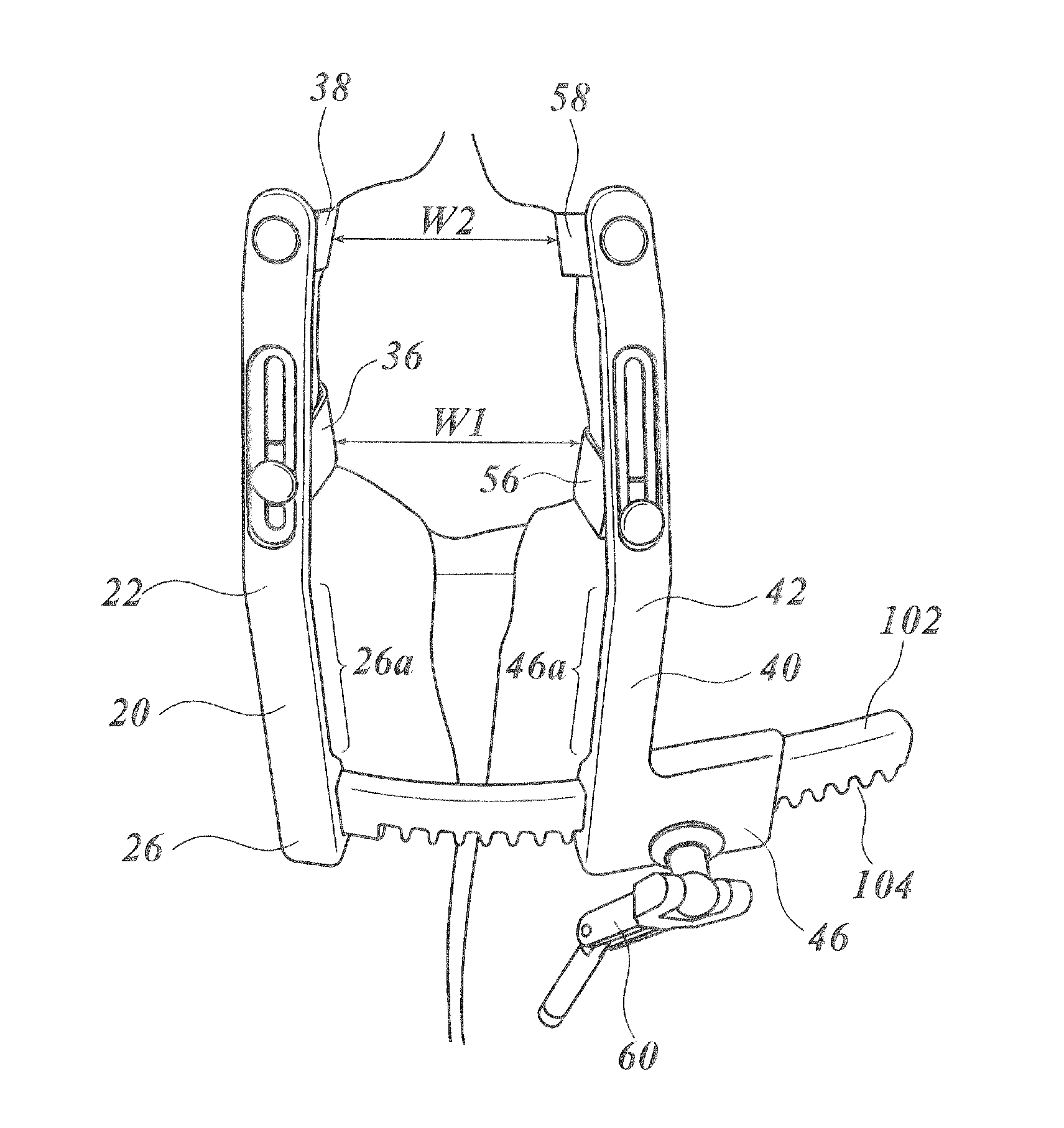
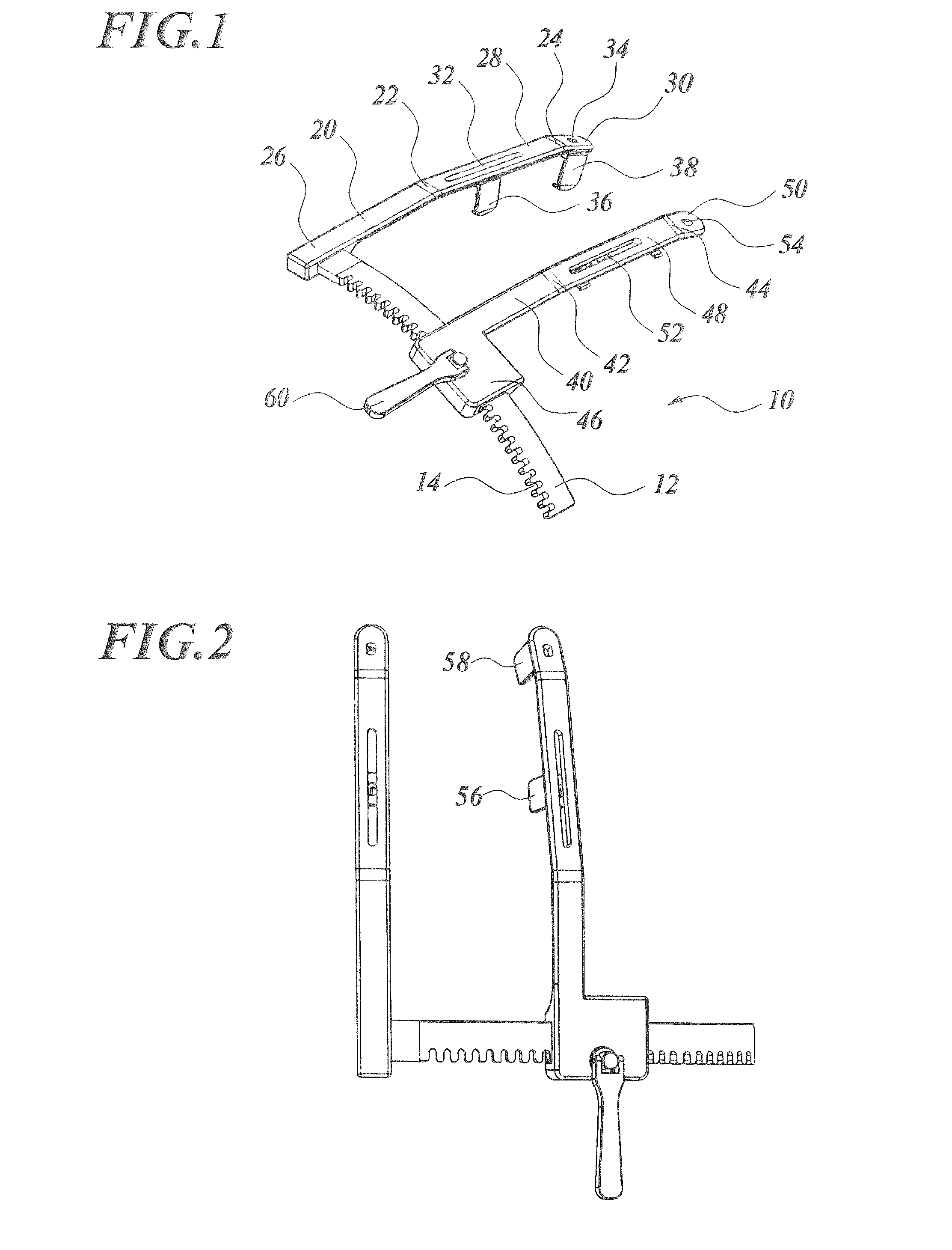
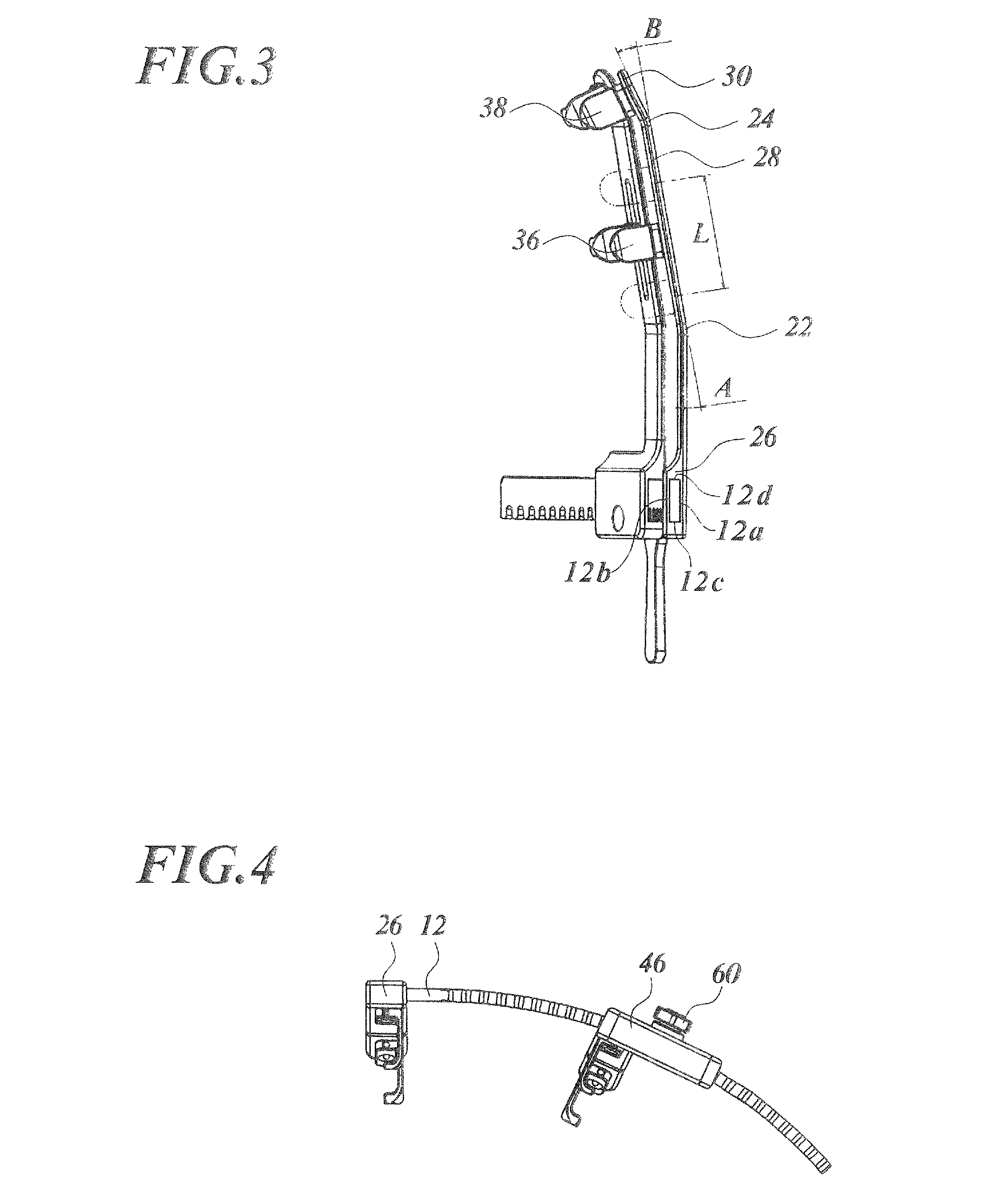
[0057]FIG. 1 is a perspective view illustrating a rib spreader according to the present invention, FIG. 2 is a plan view of the rib spreader illustrated in FIG. 1, FIG. 3 is a left side elevation of the rib spreader illustrated in FIG. 1, and FIG. 4 is a front elevation of the rib spreader illustrated in FIG. 1. Note that, in FIGS. 1 to 4, nuts for fixing the individual hooks are not illustrated.

[0058]A rib spreader 10 is configured by a stationary arm 20, a movable arm 40, and a rack 12 which relatively varies the distance between the both. The rack 12 is a thin, long plate-like component which curves archwise along a cylindrical surface. The rack 12 has teeth 14 on the side face corresponding to one short edge of the rectangular cross section taken normal to the longitudinal direction thereof. The rack 12 performs similarly to a rack in a rack-and-pinion gear mechanism. The rack 12 is fixed, on one longitudinal end face thereof, to the stationary arm 20 at a base end 26 thereof, s...

second embodiment

[0072]FIG. 11 is a perspective view illustrating a rib spreader according to the present invention. FIG. 12 is a plan view of the rib spreader illustrated in FIG. 11. FIG. 13 is a left side elevation of the rib spreader illustrated in FIG. 11. FIG. 14 is a front elevation of the rib spreader illustrated in FIG. 11.

[0073]In contrast to the rib spreader according to the first embodiment of the present invention, configured so that the nut 80 was fixed to the axial end of the hook stem 76 so as to project out from the top surface of the arm 70, the rib spreader according to the second embodiment of the present invention is improved so as to avoid hooking of surgical suture on the projection.

[0074]As seen in FIGS. 11 to 14, axial end caps 92, 96 of the intermediate hooks, and axial end caps 94, 98 of the front end hooks are integrated with the individual nuts 80 on the top surface of the nuts 80.

[0075]FIG. 15 is a cross sectional view taken along line M-M in FIG. 12. The hook stem integ...

third embodiment

[0086]FIG. 19 is a perspective view illustrating the rib spreader according to the present invention; FIG. 20 is a plan view of the rib spreader illustrated in FIG. 19; FIG. 21 is a left side elevation of the rib spreader illustrated in FIG. 19; and FIG. 22 is a front elevation of the rib spreader illustrated in FIG. 19.

[0087]As described in the above, the upper portion of heart was less readily recognizable when the rib spreaders according to the first and second embodiments of the present invention were used. But the rib spreader according to the third embodiment of the present invention was improved in the insufficient aspects regarding the field of view and operability, by using a rack 102 in place of the rack 12. In short, the rib spreader according to the second embodiment of the present invention and the rib spreader according to the third embodiment of the present invention are different in that which of the rack 12 and the rack 102 is used, and in that whether a good field ...


PUM


Abstract

Disclosed is a rib spreader including a stationary arm having a first bent portion; a first hook having a contact surface to contact with one incision plane of a sternum of human, and attached to the stationary arm ahead of the first bent portion so as to be pivotable over a predetermined angular range; a rack fixed to the base end of the stationary arm at a predetermined angle and curved archwise; a movable arm supported at the base end of the movable arm by the rack so as to be movable along the rack, to thereby vary the distance from the stationary arm; and a second hook having a contact surface to contact with the other incision plane, and is attached to the movable arm ahead of the second bent portion so as to be pivotable over a predetermined angular range.

Description

[0001]This application is a U.S. National Phase Application under 35 USC 371 of International Application PCT / JP2011 / 052852 filed Feb. 10, 2011.FIELD OF THE INVENTION[0002]The present invention relates to a rib spreader used in median sternotomy, and more specifically to a rib spreader capable of preventing fracture of sternum or crush of sternum stump which may otherwise occur during median sternotomy.DESCRIPTION OF RELATED ART[0003]Median sternotomy, by which sternum is vertically incised at the center thereof, is adopted in most medical cases in need of cardiac or macrovascular surgeries. Portions of the sternum centrally incised and split into the left and right are laterally displaced by a rib spreader, for the convenience of surgery proceeded in the thus-opened space.[0004]The median sternotomy has, however, been anticipated for a risk of sternum fracture, particularly high in children, in the process of displacement by the rib spreader. Patent Document 1 proposes a rib spread...

Claims


Application Information

Patent Timeline
Patent Type & Authority Patents(United States)
IPC IPC(8): A61B1/32A61B17/02
CPCA61B17/0206
Inventor MATSUMURA, KENICHI
Owner MEDICAL PINE
Why Eureka
Try Eureka