
Method and device for high-resolution retinal imaging

a retinal imaging and high-resolution technology, applied in the field of high-resolution retinal imaging methods and devices, can solve the problems of optical system defects not only of the eye, but also of the imaging system optical system, and achieve the effects of improving the signal-to-noise ratio of the retina image-forming device, improving the uniformity of light intensity, and improving the contrast of the retina microstructur

Active Publication Date: 2017-01-03
IMAGINE EYES
View PDF3 Cites 12 Cited by
  • Summary
  • Abstract
  • Description
  • Claims
  • Application Information

AI Technical Summary

Benefits of technology

[0020]The applicant has shown notably that, by limiting the diameter of the input pupil of the imaging system, and contrary to received wisdom, the signal-to-noise ratio of the retina image-forming device was improved and the contrast of the microstructures of the retina was thereby enhanced.
[0021]Advantageously, the input pupil of the imaging system is positioned in said predetermined plane in the input space of the imaging system, allowing for a better uniformity of the light intensity throughout the field of the image.
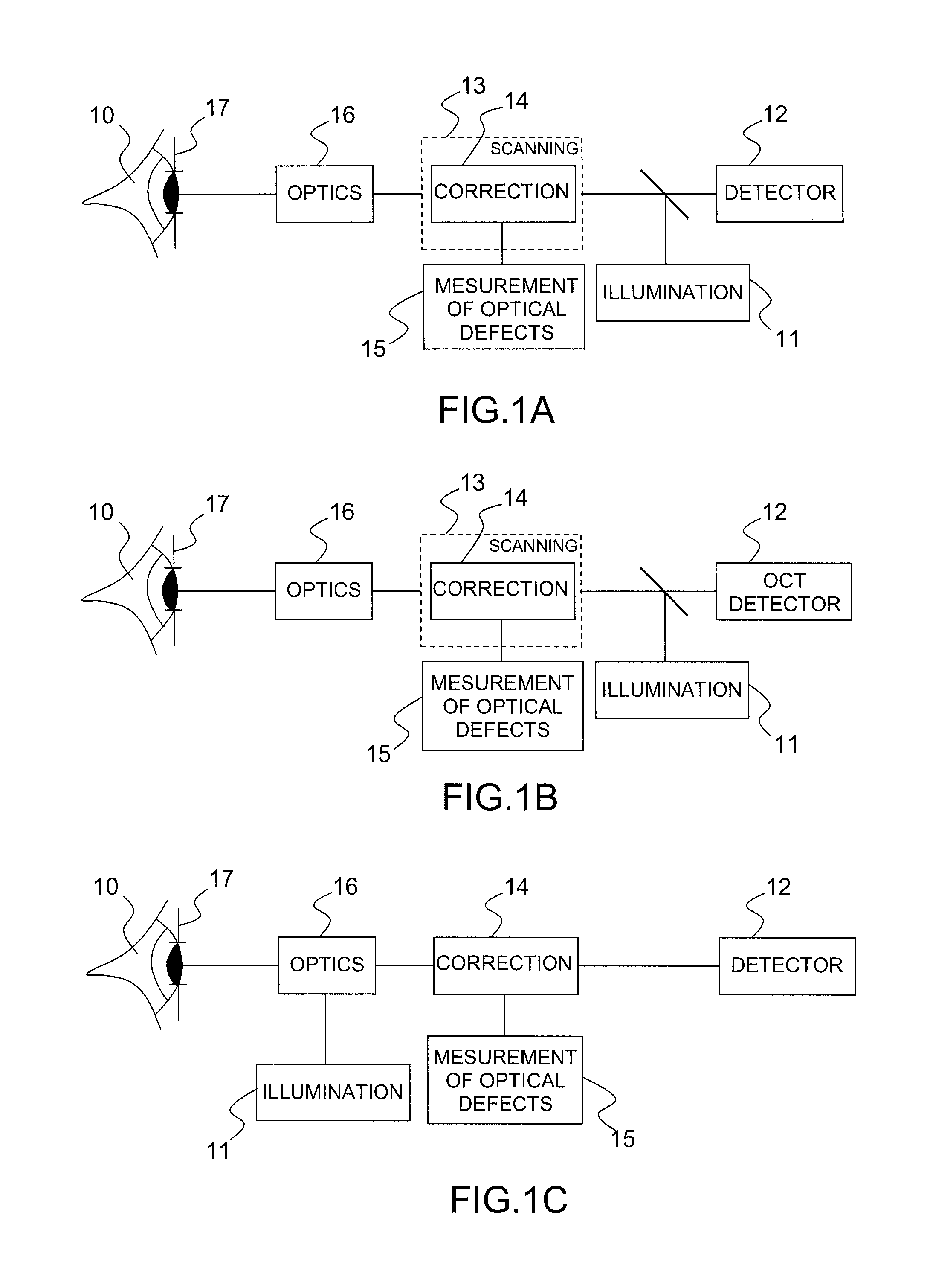
[0028]According to another variant, the device is of AOSLO type. The emission source is, according to this variant, a point source making it possible to illuminate the retina with a quasi-point illumination beam and the detection device comprises a confocal detection system. The device also comprises, according to this variant, a system for scanning said illumination beam on the retina.
[0030]Advantageously, the device for measuring optical defects is an analyzer of Shack-Hartmann type. Such a device makes it possible to analyze, in relation to nominal directions, the variation of the directions of the light rays after having passed through the optical system affected by optical defects. Such a system produces this measurement by virtue, for example, of the arrangement of a matrix detector in the focal plane of a matrix of microlenses. The duly measured variations can be directly used to control the optical defect correction device.

Problems solved by technology

These defects comprise the defects imparted by the optical system of the eye but also by the optical system of the imaging system.

Method used


Image

  • Method and device for high-resolution retinal imaging
  • Method and device for high-resolution retinal imaging
  • Method and device for high-resolution retinal imaging

Examples


Embodiment Construction

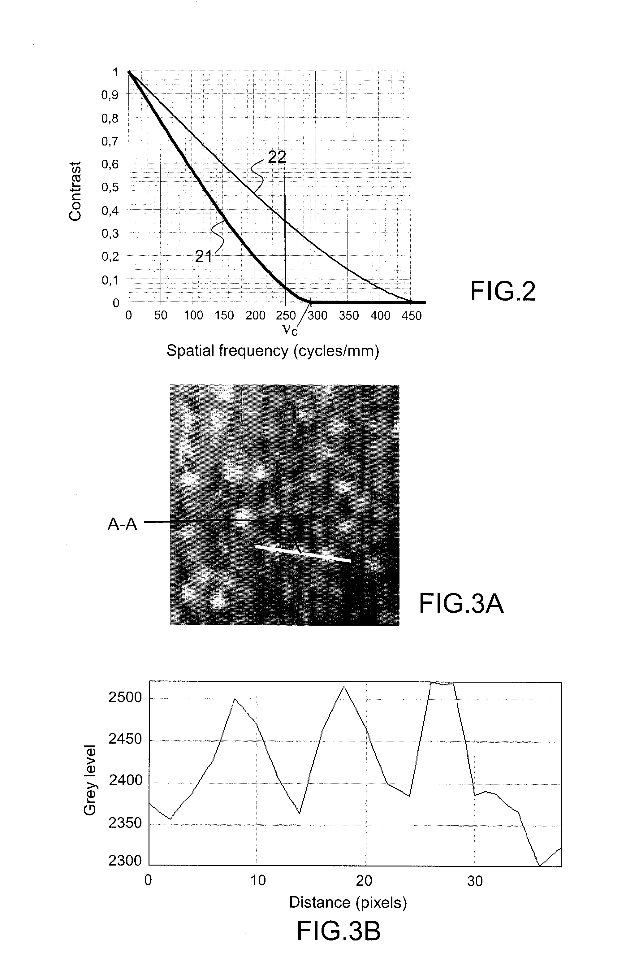
[0052]FIG. 2 represents a curve (reference 21) illustrating the modulation transfer function as a function of the frequency (given in cycles per millimeter) in a perfectly corrected optical system limited by diffraction. The value νc is the cut-off frequency, that is to say the frequency at which the contrast is zero. The cut-off frequency νc is given by:

[0053]υc=Φλ⁢⁢F(1)

[0054]Where φ is the diameter of the input pupil of the optical system, F is the focal length of the optical system and λ is the wavelength.

[0055]In a retinal imaging system of the type of those described previously, the aim is to form the image of structures of the retina, for example of the cones, photoreceptors with the dimension in proximity to the center of the fovea that is of the order of 2 μm and which are distributed in mosaic fashion with a spatial period of approximately 4 μm. Detecting the structures entails being able to resolve, using the imaging device, a spatial frequency of 250 cycles per millimeter...


PUM


Abstract

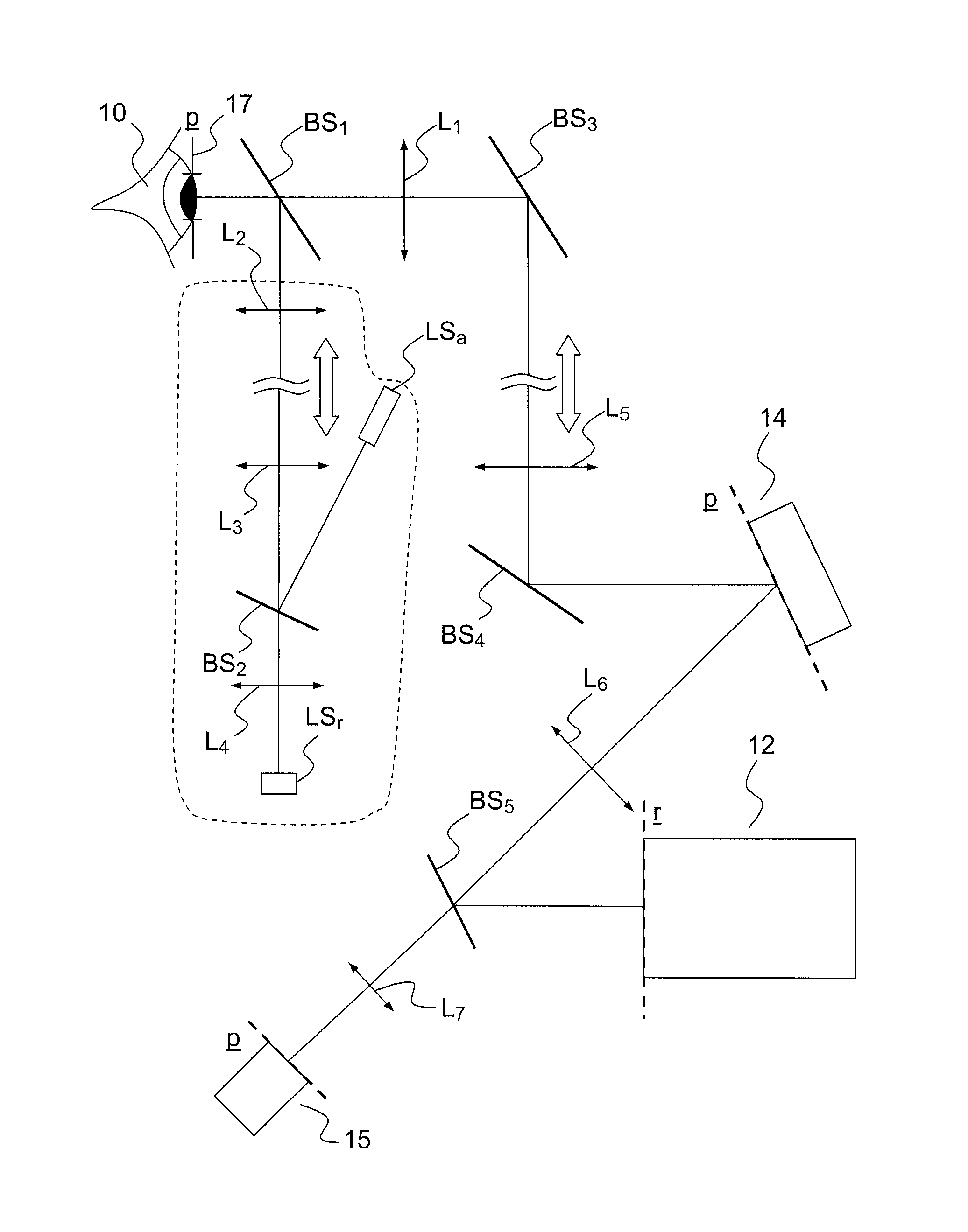
The invention relates to a high-resolution retinal imaging method and device notably comprising an emission source (LSr) for emitting a light beam for the illumination of the retina of an eye (10) of a subject, a detection device (12) capable of detecting spatial-frequency structures of 250 cycles / mm measured in the plane of the retina, an optical imaging system (16) allowing for the formation of an image of at least a part of the retina on the detection device (12), a device (15) for measuring optical defects with an analysis plane of the optical defects, a correction device (14) comprising a correction plane and intended to correct, in said correction plane, the light rays from said emission source (LSr) and backscattered by the retina as a function of the optical defects measured by the measurement device (15). The correction and analysis planes are optically conjugated with a predetermined plane (17) of the eye, and the input pupil of said optical imaging system has a diameter of between a first value Φmin and a second value Φmax, the first value being defined to allow for the detection by said detection device (12), at an imaging wavelength, of structures of the retina exhibiting a spatial frequency of 250 cycles per millimeter, and the second value being less than 5.75 mm.

Description

PRIOR ART[0001]Technical Field of the Invention[0002]The present invention relates to a high-resolution retinal imaging method and device compatible with imaging on a cellular scale.[0003]Prior Art[0004]These days, several years elapse between the start of a retinal disease and its diagnosis. This is because retinal diseases generally develop silently, causing irreversible lesions before the first clinical symptoms appear. Such is the case, for example, with Age-Related Macular Degeneration (ARMD) or glaucoma, a sickness that attacks the nerve fibers of the retina and that can cause blindness in the patient, and which is generally diagnosed when half the nerve fibers are irreparably destroyed. Now retinal diseases can be diagnosed as early as the first weeks if the retina can be imaged on a cellular scale. In practice, the first effects of retinal sicknesses affect the microscopic structures of the retina. The microstructures affected by the three retinal diseases that are most comm...

Claims


Application Information

Patent Timeline
Patent Type & Authority Patents(United States)
IPC IPC(8): A61B3/14A61B3/00A61B3/10A61B3/12
CPCA61B3/14A61B3/1015A61B3/1225
Inventor LEVECQ, XAVIERLAMORY, BARBARA
Owner IMAGINE EYES
Learn More