
High-uniformity limited-spread point spread function light emitter

a point spread function and light emitter technology, applied in the direction of light sources, lighting and heating equipment, lighting apparatus, etc., can solve the problems of non-uniform display, noticeable bright spots, design conflict in selecting the width of such simple psf functions, etc., to achieve the effect of minimalism of luminance spreading or overlap

Inactive Publication Date: 2017-01-03
A L WHITEHEAD
View PDF11 Cites 0 Cited by
  • Summary
  • Abstract
  • Description
  • Claims
  • Application Information

AI Technical Summary

Benefits of technology

The solution provides high-efficiency HDR displays with uniform light distribution, minimal luminance overlap, and reduced computational requirements, enabling visually perfect uniformity and efficient image rendering.

Problems solved by technology

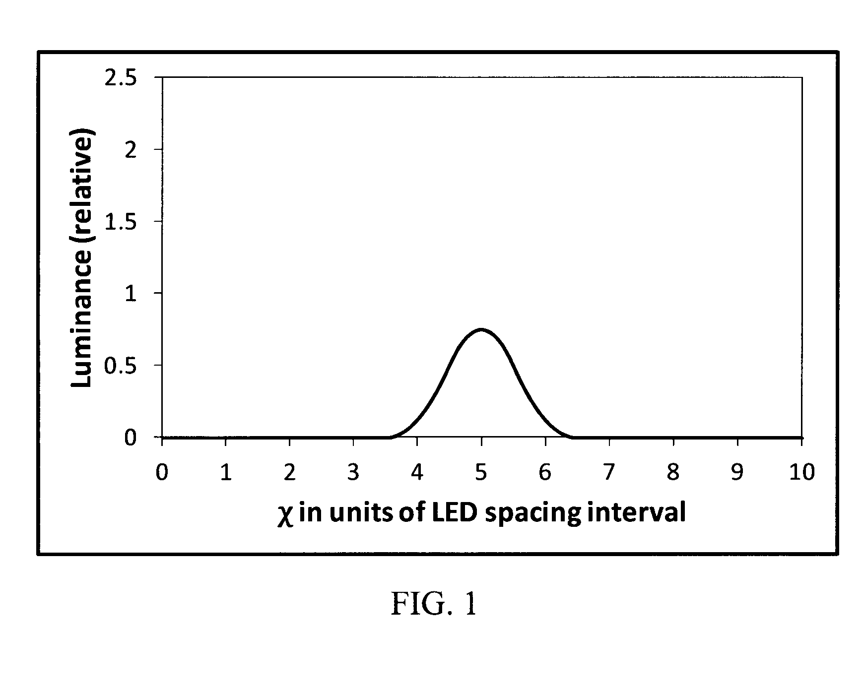
Unfortunately, there is a serious design conflict in selecting the width of such simple PSF functions.
“Hot spots” are the locations on the diffuser screen that are closest to the LED in question that have a relatively high luminance, which leads to noticeable bright spots.
In other words, the display will appear non-uniform to the human eye, thus distorting the intended image.
However, if the distance between the LED and diffuser screen is too large, the width of the luminance distribution of each LED cause it to decay too slowly with distance, which causes two problems.
First, it is no longer possible to selectively illuminate only the region near a given LED, which reduces the display efficiency in some circumstances.
Second, because of the spread, the luminance provided at any point on the diffuser screen comes from a large number of individual LEDs.
This in turn leads to a large degree of luminance overlap of adjacent LEDs within the LED array.
This is problematic, because, according to the principles of HDR displays, it is necessary to accurately predict the luminance level at each point on the diffuser screen.
If many LEDs contribute to a single luminance point, this requires substantially more computation time, which is a significant issue because that calculation must be performed in real time for each video frame.
With naturally occurring PSFs, this design conflict is a very significant problem that limits the practicality of high quality HDR displays.
The challenge is to provide a specially designed point spread function and display architecture for which the compromises listed above would be substantially less problematic.

Method used


Image

  • High-uniformity limited-spread point spread function light emitter
  • High-uniformity limited-spread point spread function light emitter
  • High-uniformity limited-spread point spread function light emitter

Examples


Embodiment Construction

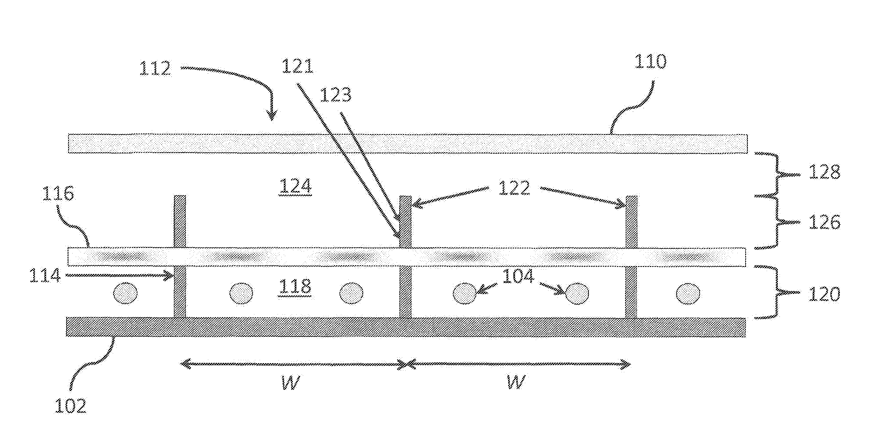
[0029]Throughout the following description specific details are set forth in order to provide a more thorough understanding to persons skilled in the art. However, well known elements may not have been shown or described in detail to avoid unnecessarily obscuring the disclosure. Accordingly, the description and drawings are to be regarded in an illustrative, rather than a restrictive, sense.

[0030]The following description is divided into two parts. The first part described in Section A is a mathematical development of the invention that develops a “minimally-spreading de-pixelization light spread function for a 2d light emitting array”, somewhat in analogy to numerical de-pixelization techniques used in digital image up-sampling. This involves three successive versions of this concept for the purpose of aiding practical and efficient emulation of the design in practical optical structures. The second part in Section B, a display architecture for emulating the “minimally-spreading de...


PUM

PropertyMeasurementUnit
reflectanceaaaaaaaaaa
Lambertian luminanceaaaaaaaaaa

Abstract

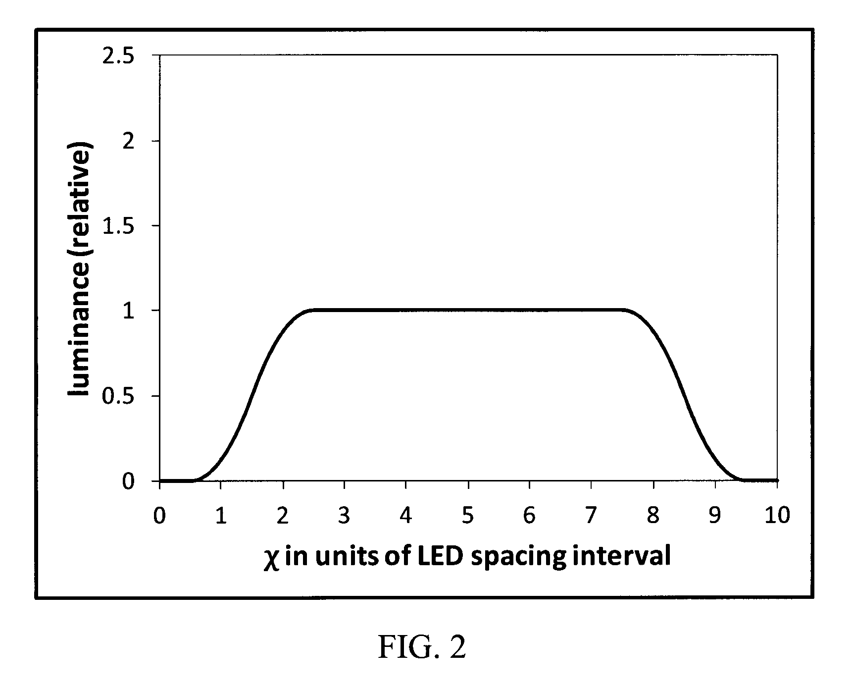
Simple yet powerful mathematical solutions are provided for producing a minimally-spreading de-pixelization light spread function with four-fold bilateral symmetry to create a High Dynamic Range LED-LCD display where the point spread functions of each LED regardless of intensity can be designed such that adjacent rows and columns of LEDs within an array blend smoothly and uniformly to create a non-pixelated continuous image in two dimensions on the diffuser screen and with minimal luminance overlap to minimize the computational demands required at video rate of an HDR display. The resulting image has substantially visually perfect uniform luminance, linear luminance and quadratic luminance gradient. Additionally a new display architecture is unveiled and described that emulates the mathematically developed light spread functions mentioned. This new architecture comprises several sub-aspects to tune the display device to the desired design requirements.

Description

CROSS-REFERENCE TO RELATED APPLICATIONS[0001]This application claims priority to U.S. Provisional Application No. 61 / 655,105, filed on 4 Jun. 2012. The entire contents of this provisional application are herein incorporated by reference.BACKGROUND OF THE INVENTION[0002]This application describes a new method of generating highly uniform, de-pixelated LED illuminated LED signs and back-lit HDR displays by employing a limited spread point spread function and new display architecture.[0003]The human eye is sensitive to light over a very wide range of intensities. Human vision is capable of discerning contrast ratios of up to 1:10,000. That is, a person can take in a scene in which some parts of the scene are 10,000 times brighter than other parts of the scene and see details in both the brightest and darkest parts of the scene. Further, human vision can adapt its sensitivity to brighter or darker scenes over a further 6 orders of magnitude.[0004]High Dynamic Range (HDR) Imaging is a te...

Claims


Application Information

Patent Timeline
Patent Type & Authority Patents(United States)
IPC IPC(8): G09F13/04G09F13/08F21K99/00G02F1/1335G09F13/22
CPCF21K9/62G02F1/133603G02F1/133605G09F13/04G02F1/133611G09F2013/222
Inventor WHITEHEAD, LORNE A.
Owner A L WHITEHEAD
Learn More