Tsunami monitoring radar system including transmitting antenna for radiating transmission signal for detecting tsunami as radio wave toward sea

a technology of tsunami monitoring and transmitting antenna, applied in the direction of instruments, machine-to-machine/machine-type communication services, wireless commuication services, etc., can solve the problems of large errors in the announced values, large cost, and insufficient detail to predict the height and arrival direction of the tsunami, so as to achieve high accuracy the prediction of the arrival time and the arrival wave height.

Active Publication Date: 2017-01-10
MITSUBISHI ELECTRIC CORP
View PDF29 Cites 2 Cited by
  • Summary
  • Abstract
  • Description
  • Claims
  • Application Information

AI Technical Summary

Benefits of technology

[0017]According to the tsunami monitoring system of the present invention, the wave height of the tsunami can be directly predicted from the flow velocity distribution of the sea surface measured by the radio wave, and therefore, it is possible to highly accurately predict the arrival time and the arrival wave height of all tsunamis including unexpected tsunami.

Problems solved by technology

However, since a location and a shift length of the fault necessary for predicting a magnitude of the generated tsunami are not accurately revealed when the earthquake occurs but subject to a data analysis at a later date, there has been a problem that large errors reside in the announced values of the magnitude, an arrival time and so on of the tsunami.
However, this method is able to only spatially obtain data of points, and therefore, this has been regarded insufficient to predict in detail a wave height and an arrival direction of the tsunami arriving in a wide range.
Further, there has been such a problem that a large cost is necessary for securing a power source and a signal propagation path.
In addition, sensors are necessary on and in the sea, and therefore, there has been such a problem that the maintenance of them are not easy.
However, the marine radar is able to measure only a sea surface flow velocity component in the line of sight of the radio wave radiated from the antenna and unable to directly measure a wave height of the arriving tsunami.

Method used


Image

  • Tsunami monitoring radar system including transmitting antenna for radiating transmission signal for detecting tsunami as radio wave toward sea
  • Tsunami monitoring radar system including transmitting antenna for radiating transmission signal for detecting tsunami as radio wave toward sea
  • Tsunami monitoring radar system including transmitting antenna for radiating transmission signal for detecting tsunami as radio wave toward sea

Examples


first embodiment

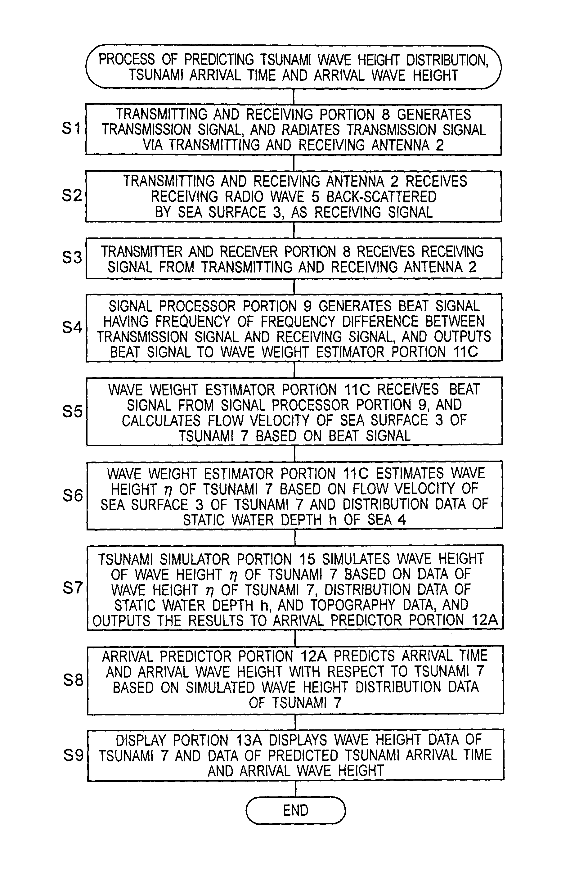
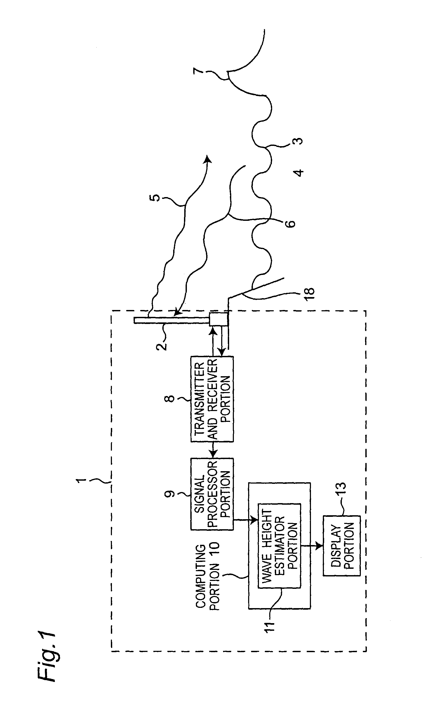
[0043]FIG. 1 is a block diagram showing a tsunami monitoring system 1 and its peripheral components, according to a first embodiment of the present invention. The tsunami monitoring system 1 of FIG. 1 is configured to include a transmitting and receiving antenna 2 provided in a position such that a transmission radio wave 5 can scan a sea surface, a transmitter and receiver portion 8, a signal processor portion 9, a computing portion 10, and a display portion 13. In addition, the computing portion 10 is configured to include a wave height estimator portion 11 configured to include a computer and a program. In addition, the transmitting and receiving antenna 2 is placed on a land 18. However, the invention is not limited thereto, the transmitting and receiving antenna 2 may be placed at any position such that the transmission radio wave 5 can scan the sea surface, for example, the transmitting and receiving antenna 2 may be placed on a sea 4. In addition, the transmitting and receivi...

second embodiment

[0067]FIG. 4 is a block diagram showing a tsunami monitoring system 1A and its peripheral components, according to a second embodiment of the present invention. As compared with the tsunami monitoring system 1 of FIG. 1, the tsunami monitoring system 1A of FIG. 4 is characterized in that a computing portion 10A is provided in place of the computing portion 10.

[0068]In addition, as compared with the computing portion 10 of FIG. 1, the computing portion 10A is characterized in that a wave height estimator portion 11A is provided in place of the wave height estimator portion 11 and a water depth distribution data memory 17 of a first memory for storing the water depth distribution data of the static water depth h of the sea 4 around the transmitting and receiving antenna 2 is further provided. In this case, although a range around the transmitting and receiving antenna 2 is arbitrarily determined depending on the range in which the transmission radio wave 5 can scan the sea surface or ...

third embodiment

[0079]The case where only the transmitting and receiving antenna 2 for measuring flow velocity Ur in the direction of the radius r is installed has been described in the second embodiment, it becomes possible to more accurately estimate the wave height η of the tsunami 7 by further installing a transmitting and receiving antenna 2 for measuring the flow velocity Vθ in the direction of the rotational angle θ.

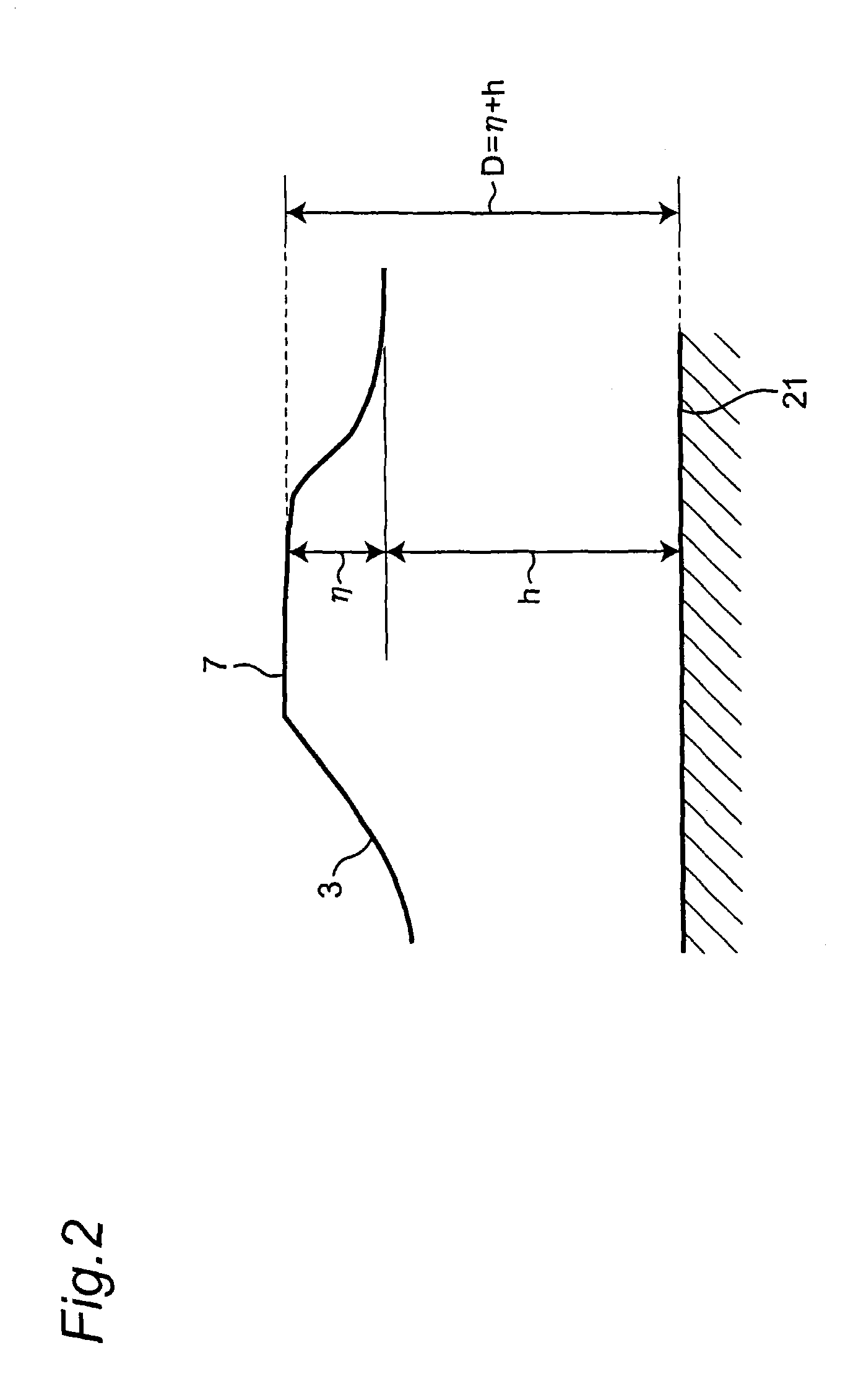
[0080]When the equations (2) and (3) of motion of the first embodiment are deformed and the dimension of the wave height η is assumed to be sufficiently small by comparison to the dimension of the total water depth D, then the following equation (8) and equation (9) are derived when D=h is substituted into the above deformed equation of motion and orderly arranged since the dimension of the total water depth D is approximately equal to the dimension of the static water depth h:

[0081]∂Mr∂t+g⁢⁢h⁢∂η∂r=0(8)∂Mθ∂t+g⁢⁢h⁢1r⁢∂η∂θ=0(9)

[0082]Next, when the equation (8) differentiated by the...


PUM


Abstract

A tsunami monitoring system includes a transmitting antenna configured to radiate a transmission signal to detect a tsunami as a radio wave toward a sea, and a receiving antenna configured to receive reflected waves reflected by the tsunami as a receiving signal. The tsunami monitoring system includes a signal generator circuit configured to generate the transmission signal having a predetermined frequency, a signal processor portion configured to generate a beat signal of a frequency difference between the transmission signal and the receiving signal, and a wave height estimator portion configured to divide a radio wave radiation region into a plurality of regions, calculate a flow velocity of a sea surface of the tsunami for each region on the basis of the beat signal, and estimate a wave height of the tsunami from a calculated flow velocity.

Description

TECHNICAL FIELD[0001]The present invention relates to a tsunami monitoring system for measuring a flow velocity of a sea surface of a tsunami by radar and predicting a wave height and arrival time to a land.BACKGROUND ART[0002]In recent years, it is concerned that a tsunami makes an incursion to a seacoast part of Japan due to an occurrence of a large earthquake. It is important to predict the arrival as early and accurate as possible in order to perform efficient evacuation behavior and handling before the tsunami arrives at the seacoast. Conventionally, several methods have been proposed to predict the arriving tsunami.[0003]For example, according to a current tsunami forecast system in the Meteorological Agency, numerical simulations of tsunami are in advance performed by setting faults that possibly generates the tsunami, and the results are accumulated as a tsunami forecast database. When an earthquake actually occurs, prediction results corresponding to the location, scale and...

Claims


Application Information

Patent Timeline
Patent Type & Authority Patents(United States)
IPC IPC(8): H04M11/04G01S13/95H04W4/22G01S13/58G01S13/50G08B21/10G01C13/00H04W4/00H04W4/02H04W4/90H04W4/029H04W4/38
CPCH04W4/22G01C13/00G01C13/002G01S13/50G01S13/58G01S13/95G08B21/10H04W4/006H04W4/027H04W4/028H04W4/38H04W4/029H04W4/90Y02A10/40Y02A50/00Y02A90/10
Inventor ISHIKAWA, HIROAKIKAWAI, TAKASHINAGANO, TAKAFUMIISONO, TAIZO
Owner MITSUBISHI ELECTRIC CORP
Why Eureka
Try Eureka