Pierceable cap

a cap and piercing technology, applied in the field of caps and vessels, can solve the problems of false positives, another opportunity for contamination, and exposure of users to harmful pathogens present in the sampl

Active Publication Date: 2017-01-17
BECTON DICKINSON & CO
View PDF10 Cites 11 Cited by
  • Summary
  • Abstract
  • Description
  • Claims
  • Application Information

AI Technical Summary

Benefits of technology

[0021]In another alternative embodiment, the frangible seal is configured so that its circumference narrows as it extends into the vessel from the cap in which it is seated. This narrowing serves a two-fold purpose of guiding the transfer device to the weakened portion for insertion through the seal and (as noted above) preventing specimen backsplash during the initial piercing. The narrowing portion may have a circumferential band, either integral to the seal or configured as an o-ring, that exerts an upward pressure on the narrowing portion, causing it to close up when the transfer device is removed from the vessel, working to substantially reseal the transfer device after sample transfer. The walls of this narrowing section may also close on each other after the initial puncture to effect resealing of the closure.
[0025]In yet another embodiment, a pierceable cap may have an elastomeric shell containing locking structures for securing the shell to a vessel, and may also have a resilient access port in the shell for allowing passage of at least part of a transfer device. The cap may also contain a frangible layer with cross slits disposed across the access port which may prevent transfer of the sample specimen through the access port before insertion of at least part of the transfer device.
[0026]The frangible layer may also have ribbed portions extending both inwardly and downwardly into the vessel which terminate in a bottom surface having weakened portions disposed thereon. These cross slits may be tearable webbed cross-slits or unjoined cross slits. The cap may also contain an o-ring configured on the shell to be disposed between the shell and a sample vessel, when the shell is seated on the sample vessel. The frangible layer and the o-ring may be one piece, and the ribbed portions of the frangible layer may serve to guide the transfer device to the slitted portions on insertion, and close upon each other when the transfer device is removed. This structural arrangement allows the slitted portion to be openable.

Problems solved by technology

While a substantially leak-proof seal may prevent specimen seepage during transport, physical removal of the cap from the vessel prior to specimen analysis presents another opportunity for contamination.
When removing the cap, any material that may have collected on the under-side of the cap during transport may come into contact with a user or equipment, possibly exposing the user to harmful pathogens present in the sample.
Another risk is the potential for creating a contaminating aerosol when the cap and the vessel are physically separated from one another, possibly leading to false positives or exaggerated results in other specimens being simultaneously or subsequently assayed in the same general work area through cross-contamination.
Since amplification is intended to enhance assay sensitivity by increasing the quantity of targeted nucleic acid sequences present in a specimen, transferring even a minute amount of specimen from another container, or target nucleic acid from a positive control sample, to an otherwise negative specimen could result in a false-positive result.
Certain caps with only a frangible layer, such as foil, covering the vessel opening may cause contamination by jetting droplets of the contents of the vessel into the surrounding environment when pierced.
In addition, temperature changes can lead to a sealed collection vessel with a pressure greater than the surrounding air, which is released when the cap is punctured.
Other existing systems have used absorptive penetrable materials above a frangible layer to contain any possible contamination, but the means for applying and retaining this material adds cost.
In other systems, caps may use precut elastomers for a pierceable seal, but these caps may tend to leak.
Other designs with valve type seals have been attempted, but the valve type seals may cause problems with dispense accuracy.

Method used


Image

  • Pierceable cap
  • Pierceable cap
  • Pierceable cap

Examples


Embodiment Construction

[0077]Some embodiments of the invention are discussed in detail below. While specific example embodiments may be discussed, it should be understood that this is done for illustration purposes only. A person skilled in the relevant art will recognize that other components and configurations may be used without parting from the spirit and scope of the invention.

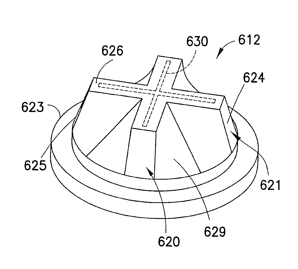
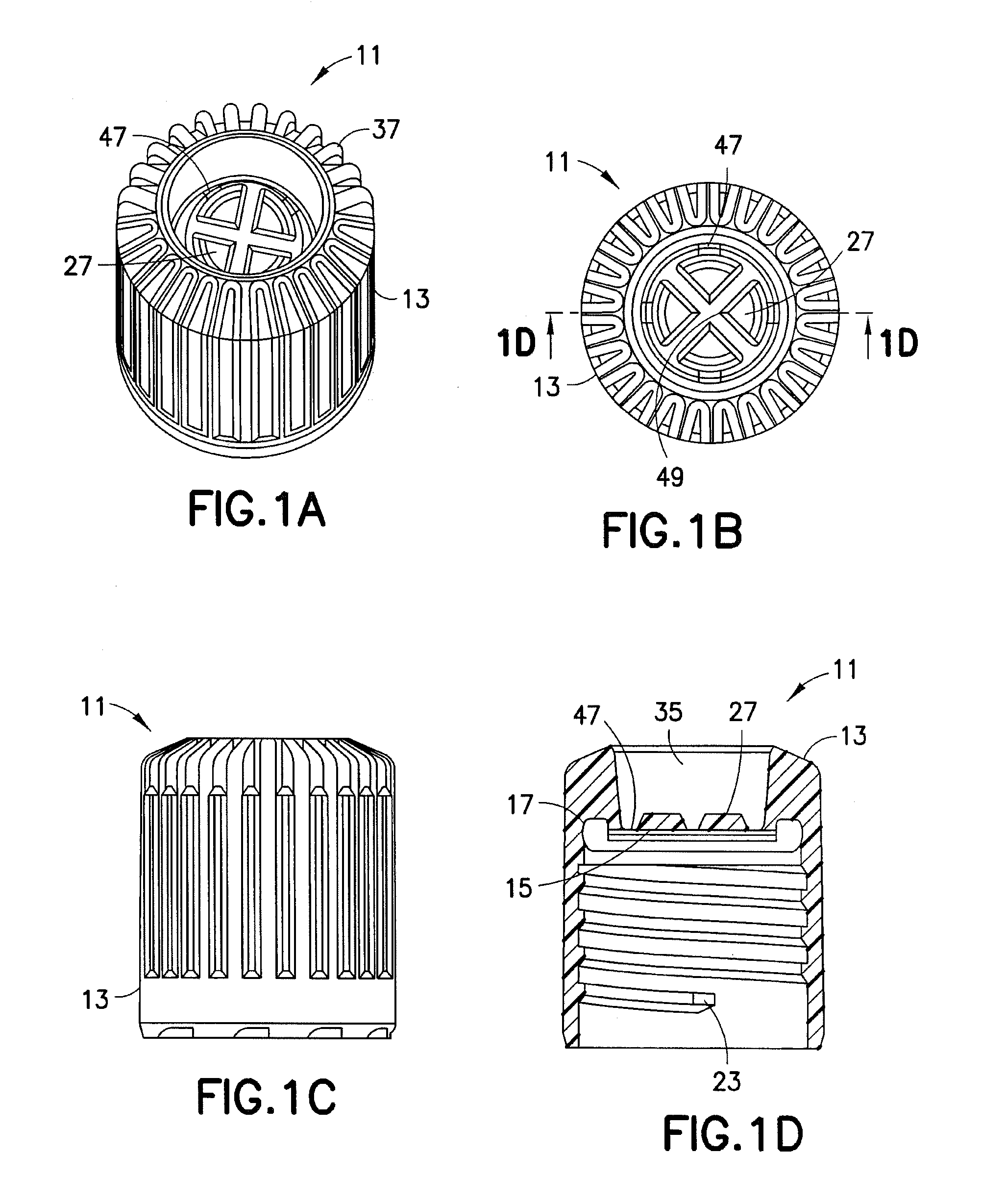
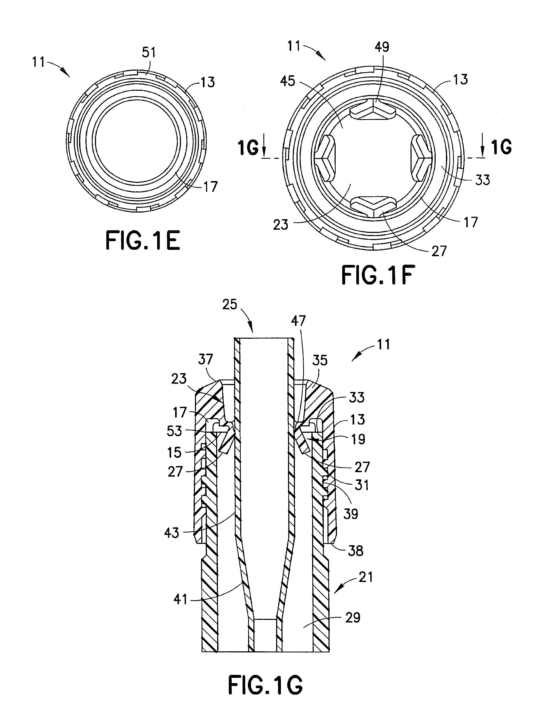
[0078]Embodiments of the present invention may include a pierceable cap for closing a vessel containing a sample specimen. The sample specimen may include diluents for transport and testing of the sample specimen. A transfer device, such as, but not limited to, a pipette, may be used to transfer a precise amount of sample from the vessel to testing equipment. A pipette tip may be used to pierce the pierceable cap. A pipette tip is preferably plastic, but may be made of any other suitable material. Scoring the top of the vessel can permit easier piercing. The sample specimen may be a liquid patient sample or any other suitable s...


PUM


Abstract

A pierceable cap 11 may be used for containing sample specimens. The pierceable cap 11 may prevent escape of sample specimens before transfer with a transfer device 43. The pierceable cap 11 may fit over a vessel 21. An access port in the shell of the pierceable cap 11 may allow passage of a transfer device 43 through the pierceable cap 11. At least one frangible layer 215, 216 may be configured with cross slits 506 in a particular cross slit geometry. The cross slits 506 may contain an openable portion 644 or be covered by a thin membrane 645. The shell 610 and frangible layer (s) 215, 216 may be integrated into a one piece cap 601, or be separate components 634. The membrane on which the cross slits 506 are placed can be flat or contoured to guide the transfer device 43 to the cross slits 506.

Description

CROSS REFERENCE TO RELATED APPLICATIONS[0001]Commonly owned U.S. patent application Ser. No. 11 / 785,144, filed Apr. 16, 2007, entitled “Pierceable Cap” and Ser. No. 11 / 979,713, filed Nov. 7, 2007, entitled “Pierceable Cap” are related to this application and incorporated by reference herein in their entirety. This application claims the benefit of the filing date of U.S. Provisional Patent Application Nos. 61 / 442,676 and 61 / 442,634 filed Feb. 14, 2011, the disclosures of which are hereby incorporated herein by reference.BACKGROUND OF THE INVENTION[0002]Combinations of caps and vessels are commonly used for receiving and storing specimens. In particular, biological and chemical specimens may be analyzed to determine the existence of a particular biological or chemical agent. Types of biological specimens commonly collected and delivered to clinical laboratories for analysis may include blood, urine, sputum, saliva, pus, mucous, cerebrospinal fluid, and others. Since these specimen ty...

Claims


Application Information

Patent Timeline
Patent Type & Authority Patents(United States)
IPC IPC(8): B01L3/00B65D51/00
CPCB01L3/56B65D51/002B65D2231/022Y10T436/2575
Inventor LENTZ, AMMON DAVIDBAILEY, KEVINDIEMERT, DUSTINKRAYER, JOEL DANIELVAUGHAN, LAURENCE MICHAEL
Owner BECTON DICKINSON & CO
Why Eureka
Try Eureka