
System and method for monitoring and control of cavitation in positive displacement pumps

a technology of cavitation monitoring and control, applied in the direction of pump control, positive displacement liquid engine, fluid parameter, etc., can solve problems such as machine failure, and achieve the effect of simplifying the severity ratio

Active Publication Date: 2017-01-17
CIRCOR PUMPS NORTH AMERICA LLC
View PDF27 Cites 126 Cited by
  • Summary
  • Abstract
  • Description
  • Claims
  • Application Information

AI Technical Summary

Problems solved by technology

One downside to manual monitoring is that typically it is only performed periodically.
Thus, if an adverse condition arises between inspections, machinery failure can occur.

Method used


Image

  • System and method for monitoring and control of cavitation in positive displacement pumps
  • System and method for monitoring and control of cavitation in positive displacement pumps
  • System and method for monitoring and control of cavitation in positive displacement pumps

Examples


Embodiment Construction

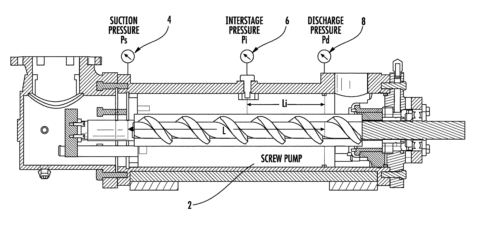
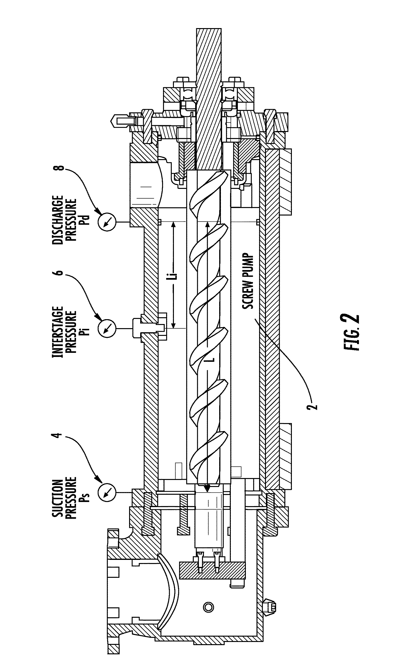
[0013]In positive displacement screw pumps, pressure is developed from the inlet or suction port of the pump to the outlet or discharge port in stage-to-stage increments. Each stage is defined as a moving-thread closure or isolated volume formed by the meshing of pump rotors between the inlet and outlet ends of the pump. Pressure is developed along the moving-thread closures as liquid progresses through the pump. The number of closures is usually proportional to the desired level of outlet pressure delivered, i.e., the greater the pressure, the greater the number of closures necessary. The closures enable the pump to develop an internal pressure gradient of progressively increasing pressure increments. Properly applied, a rotary axial-screw pump can be used to pump a broad range of fluids, from high-viscosity liquids to relatively light fuels or water / oil emulsions.

[0014]When entrained or dissolved gas exist in solution within the pump, the normal progression of pressure gradient de...


PUM


Abstract

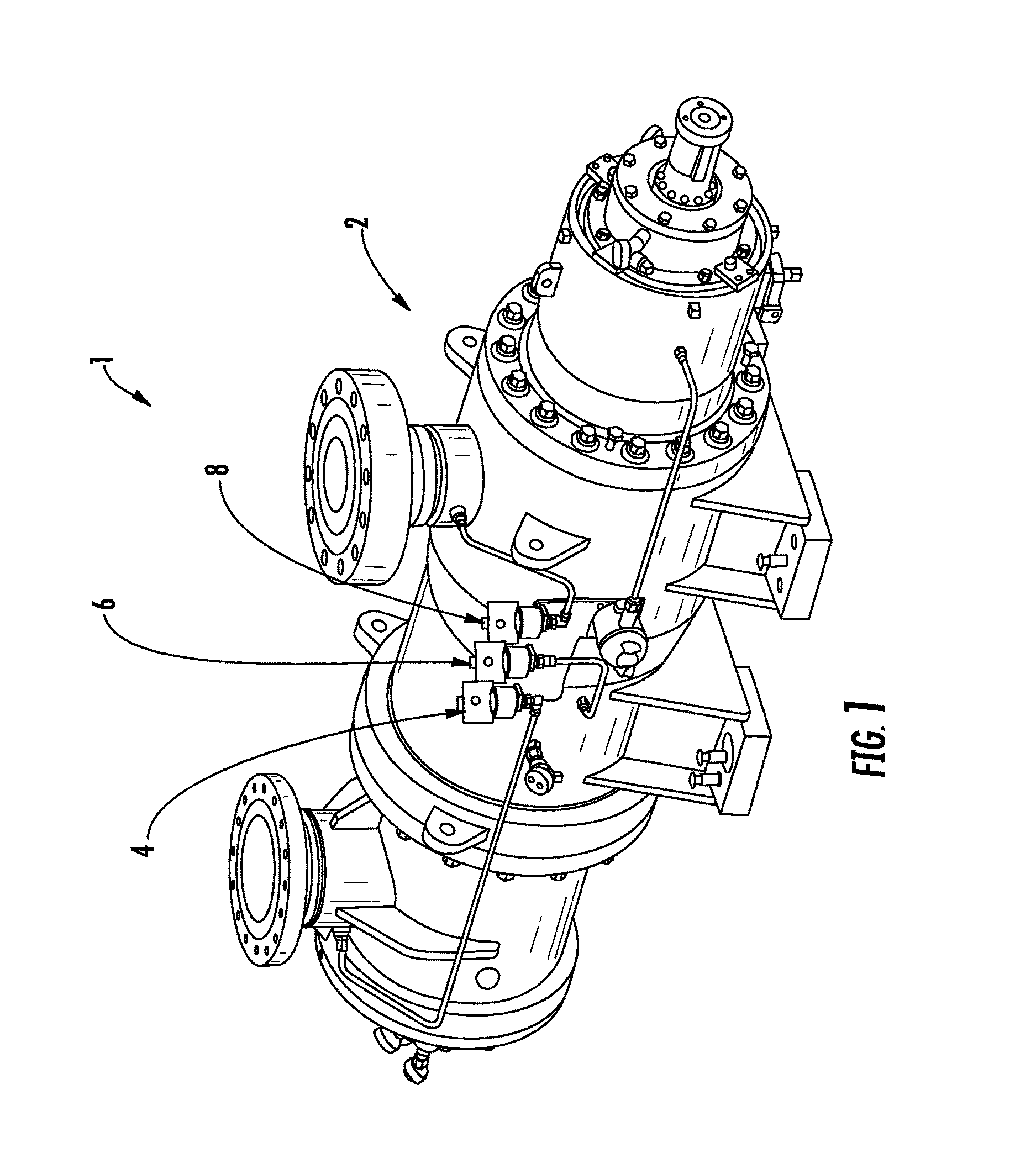
A system and method are disclosed for monitoring and controlling a positive displacement pump using readings obtained from a plurality of pressure sensors. The pressure sensors may be mounted at the suction, discharge and interstage regions of the pump. Signals from the pressure sensors are compared to obtain a ratio that is used to predict whether a cavitation condition exists within the pump. The ratio can be compared to user provided limits to change an operating characteristic of the pump to reduce predicted cavitation. The pump may be stopped, or pump speed changed, when the ratio is less than a predetermined value. In some embodiments, historical information regarding the ratio may be used to obtain standard deviation information which may then be used to predict whether gas bubbles are passing through the pump. Other embodiments are described and claimed.

Description

FIELD OF THE DISCLOSURE[0001]The disclosure is generally related to the field of monitoring systems for machinery, and more particularly to an improved system and method for monitoring pump cavitation and for controlling pump operation based on such monitoring.BACKGROUND OF THE DISCLOSURE[0002]The condition of rotating machinery is often determined using visual inspection techniques performed by experienced operators. Failure modes such as cracking, leaking, corrosion, etc. can often be detected by visual inspection before failure is likely. The use of such manual condition monitoring allows maintenance to be scheduled, or other actions to be taken, to avoid the consequences of failure before the failure occurs. Intervention in the early stages of deterioration is usually much more cost effective than undertaking repairs subsequent to failure.[0003]One downside to manual monitoring is that typically it is only performed periodically. Thus, if an adverse condition arises between insp...

Claims


Application Information

Patent Timeline
Patent Type & Authority Patents(United States)
IPC IPC(8): F04B49/02F04B49/06F04B49/00F04B49/08F04C14/28
CPCF04B49/022F04B49/00F04B49/06F04B49/08F04C14/28F04B2205/01F04B2205/03F04B2205/05F04B2205/07F04C2270/18F04C2270/86
Inventor YIN, DAN
Owner CIRCOR PUMPS NORTH AMERICA LLC
Learn More