Optical scanner and image forming apparatus
a technology which is applied in the field of optical scanner and image forming apparatus, can solve the problems of difficult to sufficiently suppress stiff support frame, etc., and achieve the effect of suppressing the light reflecting plate from being bent and stiff support fram
- Summary
- Abstract
- Description
- Claims
- Application Information
AI Technical Summary
Benefits of technology
Problems solved by technology
Method used
Image
Examples
first embodiment
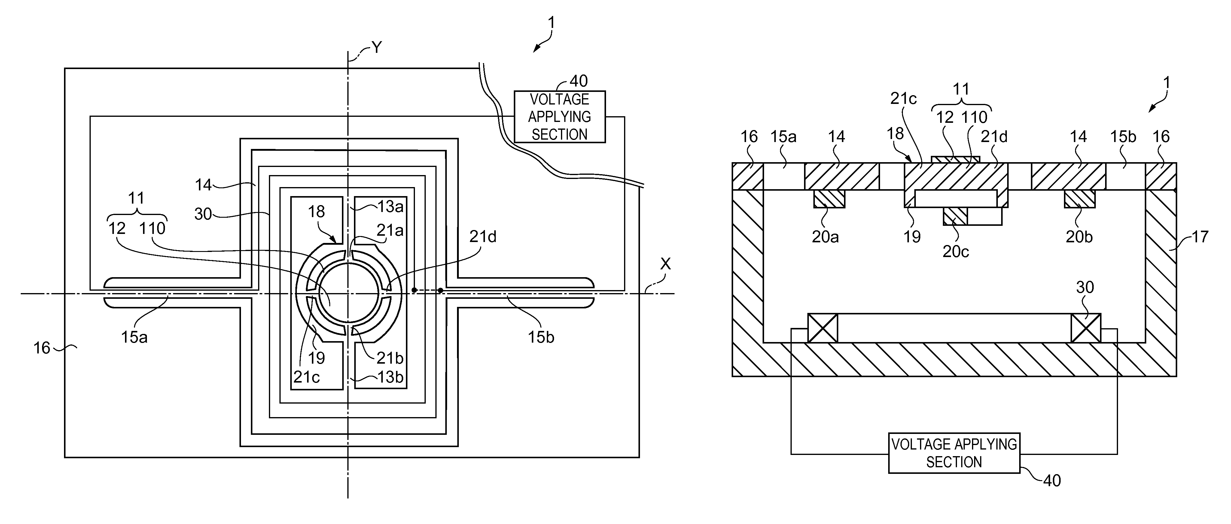
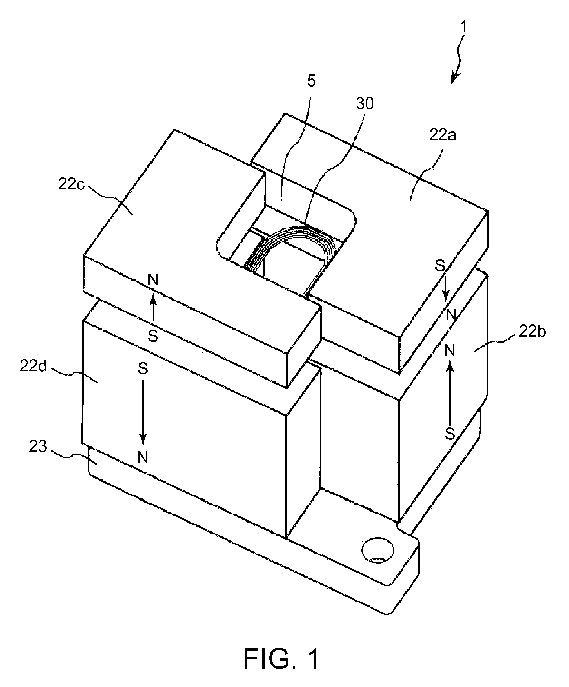
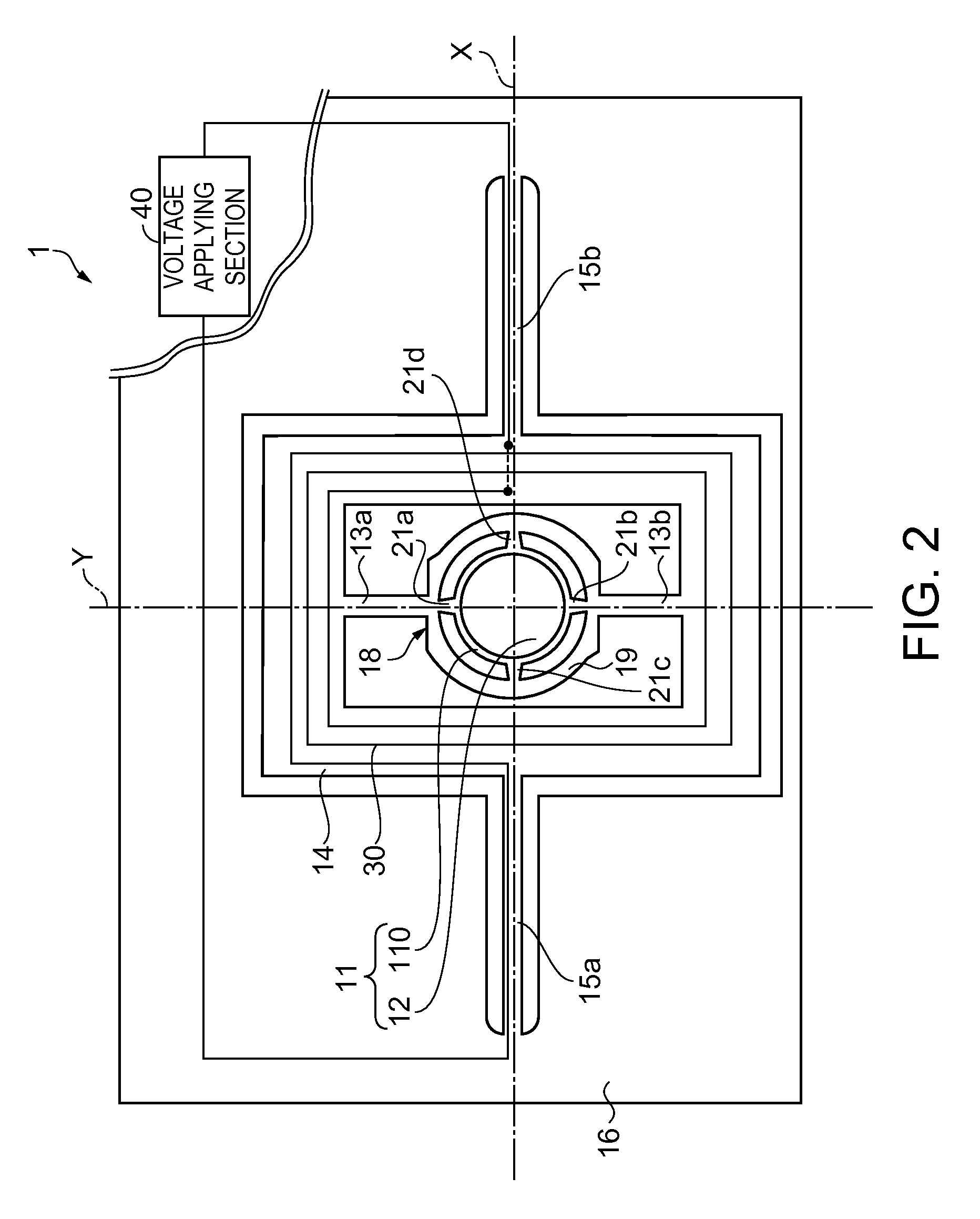
[0045]FIG. 1 is a perspective view illustrating a first embodiment of an optical scanner according to the invention, FIG. 2 is a plan view illustrating a movable section, each shaft member, a frame-shaped member, a coil and the like of the optical scanner shown in FIG. 1, FIG. 3 is a cross-sectional view illustrating the movable section of the optical scanner shown in FIG. 1, FIG. 4 is a block diagram illustrating a voltage applying section of a drive unit provided in the optical scanner shown in FIG. 1, FIGS. 5A and 5B are diagrams illustrating an example of voltage generated in a first voltage generating section and a second voltage generating section shown in FIG. 4. Hereinafter, for ease of description, an upper side in FIGS. 1 and 3 is referred to as “up”, a lower side therein is referred to as “down”, a right side therein is referred to as “right”, and a left side therein is referred to as “left”. Further, a front side on the plane in FIG. 2 is referred to as “up”, a rear side...
second embodiment
[0097]FIG. 6 is a plan view illustrating a movable section, each shaft member, a coil and the like in a second embodiment of an optical scanner according to the invention. Hereinafter, for ease of description, a front side on the plane in FIG. 6 is referred to as “up”, a rear side thereon is referred to as “down”, a right side thereon is referred to as “right”, and a left side thereon is referred to as “left”.
[0098]Hereinafter, in the second embodiment, different points from the above-described first embodiment will be mainly described, and the same configuration will not be described.
[0099]As shown in FIG. 6, an optical scanner 1 according to the second embodiment includes a substrate 23, a movable section 18, a pair of shaft members (first shaft members) 13a and 13b, a support member 16, four permanent magnets 22a, 22b, 22c and 22d, a coil 30 that generates a magnetic field by application of voltage, and a voltage applying section 40 that applies voltage to the coil 30 (see FIG. 1...
third embodiment
[0107]FIG. 7 is a plan view illustrating a third embodiment of an optical scanner according to the invention, and FIG. 8 is a cross-sectional view taken along line A-A in FIG. 7.
[0108]Hereinafter, for ease of description, a front side on the plane in FIG. 7 is referred to as “up”, a rear side thereon is referred to as “down”, a right side thereon is referred to as “right”, and a left side thereon is referred to as “left”. An upper side in FIG. 8 is referred to as “up”, a lower side therein is referred to as “down”, a right side therein is referred to as “right”, and a left side therein is referred to as “left”.
[0109]Hereinafter, with respect to the third embodiment, different points from the above-described first embodiment will be mainly described, and the same configuration will not be described.
[0110]As shown in FIGS. 7 and 8, an optical scanner 1 according to the third embodiment includes a movable section 18, a pair of shaft members (second shaft members) 13a and 13b, a frame-s...
PUM
 Abstract
Description
Claims
Application Information
 - R&D
- Intellectual Property
- Life Sciences
- Materials
- Tech Scout
- Unparalleled Data Quality
- Higher Quality Content
- 60% Fewer Hallucinations
Browse by: Latest US Patents, China's latest patents, Technical Efficacy Thesaurus, Application Domain, Technology Topic, Popular Technical Reports.
© 2025 PatSnap. All rights reserved.Legal|Privacy policy|Modern Slavery Act Transparency Statement|Sitemap|About US| Contact US: help@patsnap.com


