Antenna mount assembly

a technology of mounting brackets and mounting brackets, applied in the field of telecommunication equipment technology, can solve the problems of large number of poles with unused, large backlash, installation of additional cell towers, etc., and achieve the effect of efficient and elegan

Active Publication Date: 2017-01-24
MICRO WIRELESS SOLUTIONS CORP
View PDF42 Cites 2 Cited by
  • Summary
  • Abstract
  • Description
  • Claims
  • Application Information

AI Technical Summary

Benefits of technology

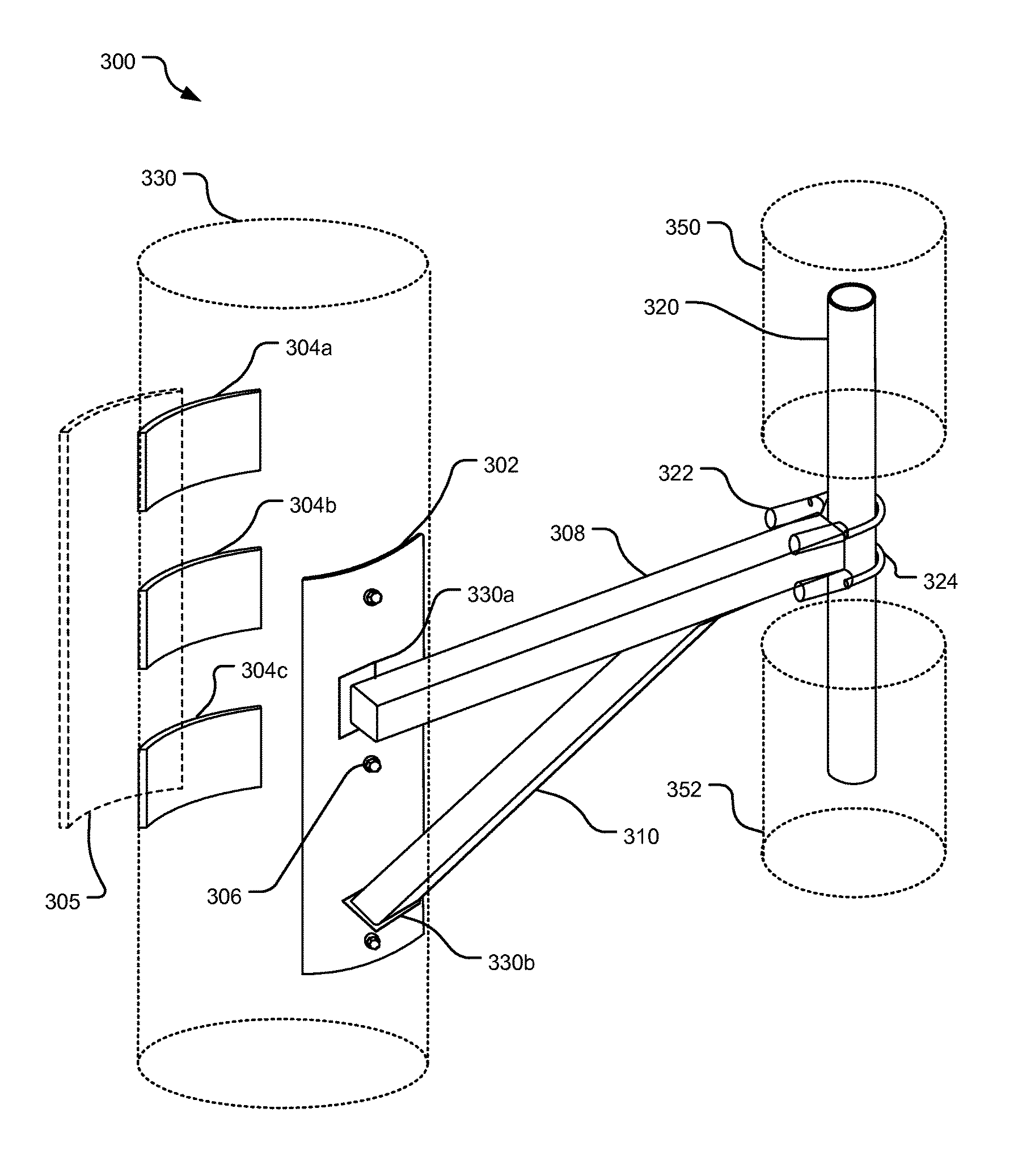
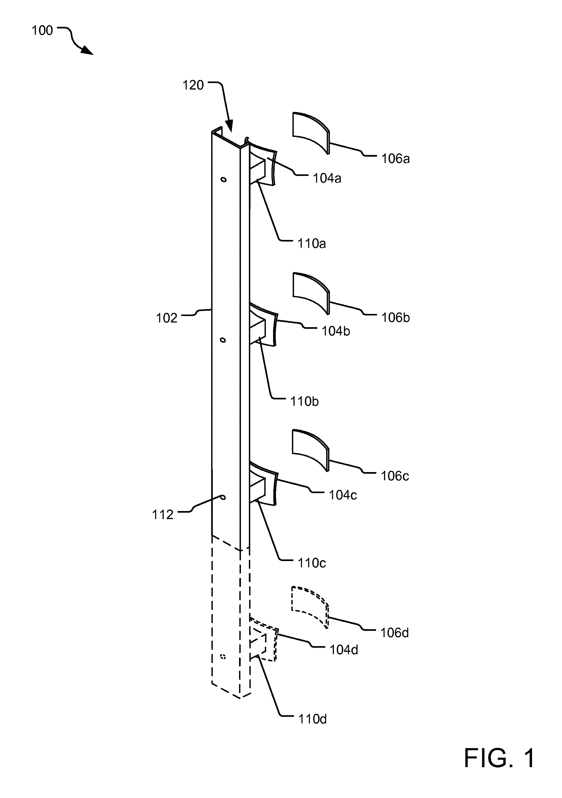
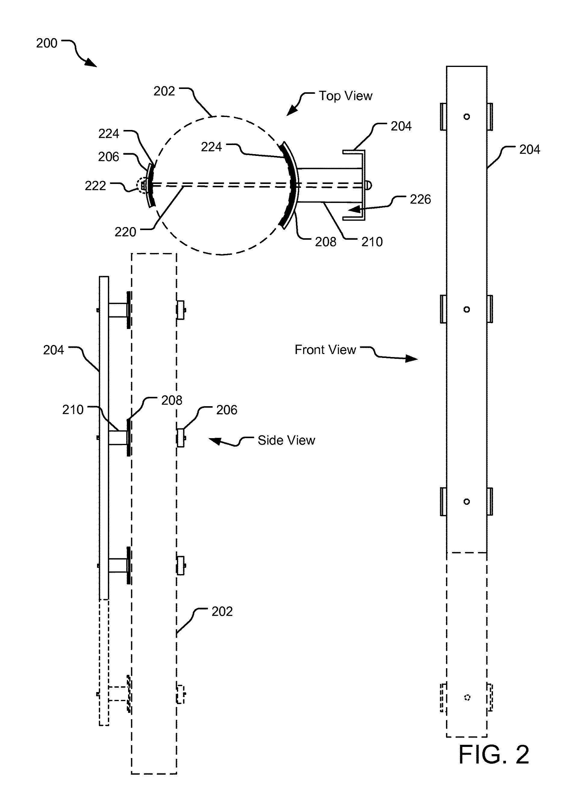
[0004]An antenna mount assembly disclosed herein provides for an efficient and elegant solution for installation of radio frequency antennas on existing wooden poles. An implementation of the antenna mount assembly includes a saddle comprising a plurality of concave plates, each of the plurality of concave plates configured to be attached to a pole. A pipe mount attachment element is welded to one of the plurality of concave plates. A pipe mount is attached to the pipe mount attachment element and the pipe mount is configured to attach an antenna element thereto.
[0005]Implementations of the antenna mount assemblies disclosed herein improve the ease and functionality of applying wireless antennas for “Small Cell Technology” to existing wood distribution poles within existing communities and industrial settings. Specifically, one or more of these implementations provide stealth like design with “low visual impact” combined with quick installation, which can be performed by a single user. An example of the antenna mount assembly disclosed herein provides light weight design including antenna mount brackets coupled with the carriage bolt with front locking system, which allows a user to assemble the bracket only needing to tighten the bolt on one side of the distribution pole. For example, for an antenna mount bracket including three saddle plates, this exercise is completed three times and the bracket is installed in place in under twenty (20) minutes. The antenna mount assembly may further include front mounting plate containing two (2) holes used for set screws, which allows a contractor to line up the front mounting plate to pre drilled holes in a wooden pole prior to mounting the antenna mount assembly.

Problems solved by technology

Given the ubiquitous presence of telecommunication equipment, there has been considerable backlash, especially in residential communities, against installation of additional cell towers, etc.
On the other hand, existing utility companies with their overhead power distribution systems have a large number of poles with unused installation space.
Furthermore, there is limited space and capacity and therefore, the telecommunication companies have to take into consideration the efficient utilization of space, installation time, ease of installation, durability of equipment mounts, aesthetics, etc.

Method used


Image

  • Antenna mount assembly
  • Antenna mount assembly
  • Antenna mount assembly

Examples


Embodiment Construction

[0023]In the following description, for the purposes of explanation, numerous specific details are set forth in order to provide a thorough understanding of the present invention. It will be apparent, however, to one skilled in the art that the present invention may be practiced without some of these specific details. For example, while various features are ascribed to particular embodiments, it should be appreciated that the features described with respect to one embodiment may be incorporated with other embodiments as well. By the same token, however, no single feature or features of any described embodiment should be considered essential to the invention, as other embodiments of the invention may omit such features.

[0024]In the interest of clarity, not all of the routine functions of the implementations described herein are shown and described. It will, of course, be appreciated that in the development of any such actual implementation, numerous implementation-specific decisions ...


PUM


Abstract

An antenna mount assembly disclosed herein provides for an efficient and elegant solution for installation of radio frequency antennas on existing wooden poles. An implementation of the antenna mount assembly includes a saddle comprising a plurality of concave plates, each of the plurality of concave plates configured to be attached to a pole. A pipe mount attachment element is welded to one of the plurality of concave plates. A pipe mount is attached to the pipe mount attachment element and the pipe mount is configured to attach an antenna element thereto.

Description

FIELD[0001]Implementations disclosed herein relate, in general, to the telecommunication equipment technology and specifically to technology for antenna mount equipment.DISCUSSION OF RELATED ART[0002]Telecommunication and information technology are as essential technologies for all modern economies. Due to advances in wireless technologies, consumers and business have come to rely on availability of access to information and content at all times. The increased amount of content being conveyed on the wireless communication spectrum makes it necessary to deploy a larger number of sites to increase the network footprint throughout cities across the nation to satisfy the bandwidth demands. As a result, telecommunication companies utilize all available avenues for installing antennas for receiving and transmitting signals.[0003]Given the ubiquitous presence of telecommunication equipment, there has been considerable backlash, especially in residential communities, against installation of...

Claims


Application Information

Patent Timeline
Patent Type & Authority Patents(United States)
IPC IPC(8): A47B96/06F21V35/00F21V21/00E04G5/06E04G3/00H01Q1/12A47K1/00A47G29/00F16M13/02H01Q9/34F16M11/20F16M13/00
CPCH01Q1/1228F16M13/02F16M11/2014H01Q1/12H01Q1/125H01Q1/1207H01Q1/1242F16M13/022
Inventor DIPIERO, MICHAEL J.
Owner MICRO WIRELESS SOLUTIONS CORP
Why Eureka
Try Eureka