Manufacturing of segmented wind turbine blade

a wind turbine and blade technology, applied in the field of manufacturing a wind turbine blade, can solve the problems of increasing manufacturing and transportation costs of wind turbine blades, and achieve the effect of convenient and efficient assembly

Pending Publication Date: 2022-01-20
BLADE DYNAMICS LTD +1
View PDF6 Cites 1 Cited by
  • Summary
  • Abstract
  • Description
  • Claims
  • Application Information

AI Technical Summary

Benefits of technology

[0009]This method provides an improved and efficient way of segmenting and re-assembling wind turbine blades. Preferably, the method further comprises a step of arranging a spar structure within one of the shell halves prior to closing and joining the shell halves.
[0018]By manufacturing the wind turbine blade using a spar structure comprising a first part and a second part, releasably coupled to each other, an efficient and elegant method is provided for segmenting and re-assembling such wind turbine blade, including uncoupling and preferably re-coupling said parts.
[0054]In another aspect, the present invention relates to a wind turbine blade obtainable by the method according to the present invention. The present wind turbine blade can be easily and efficiently assembled due to its spar structure and its coupling and de-coupling properties.

Problems solved by technology

As the size of wind turbines increases, the manufacturing and transporting of wind turbine blades becomes more challenging and costly.
However, a number of challenges may be associated with such design, relating to the manufacturing and joining of the shell segments including load bearing structures such as spar beams, shear webs or other internal components.

Method used


Image

  • Manufacturing of segmented wind turbine blade
  • Manufacturing of segmented wind turbine blade
  • Manufacturing of segmented wind turbine blade

Examples


Embodiment Construction

[0059]The invention is explained in detail below with reference to an embodiment shown in the drawings, in which

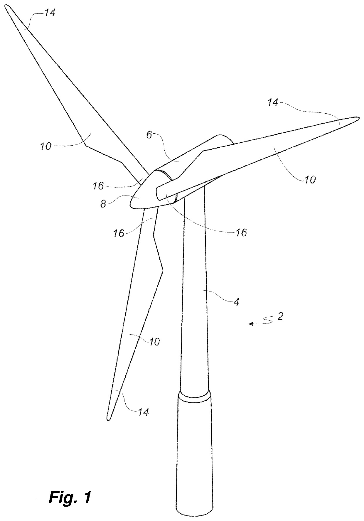
[0060]FIG. 1 shows a wind turbine,

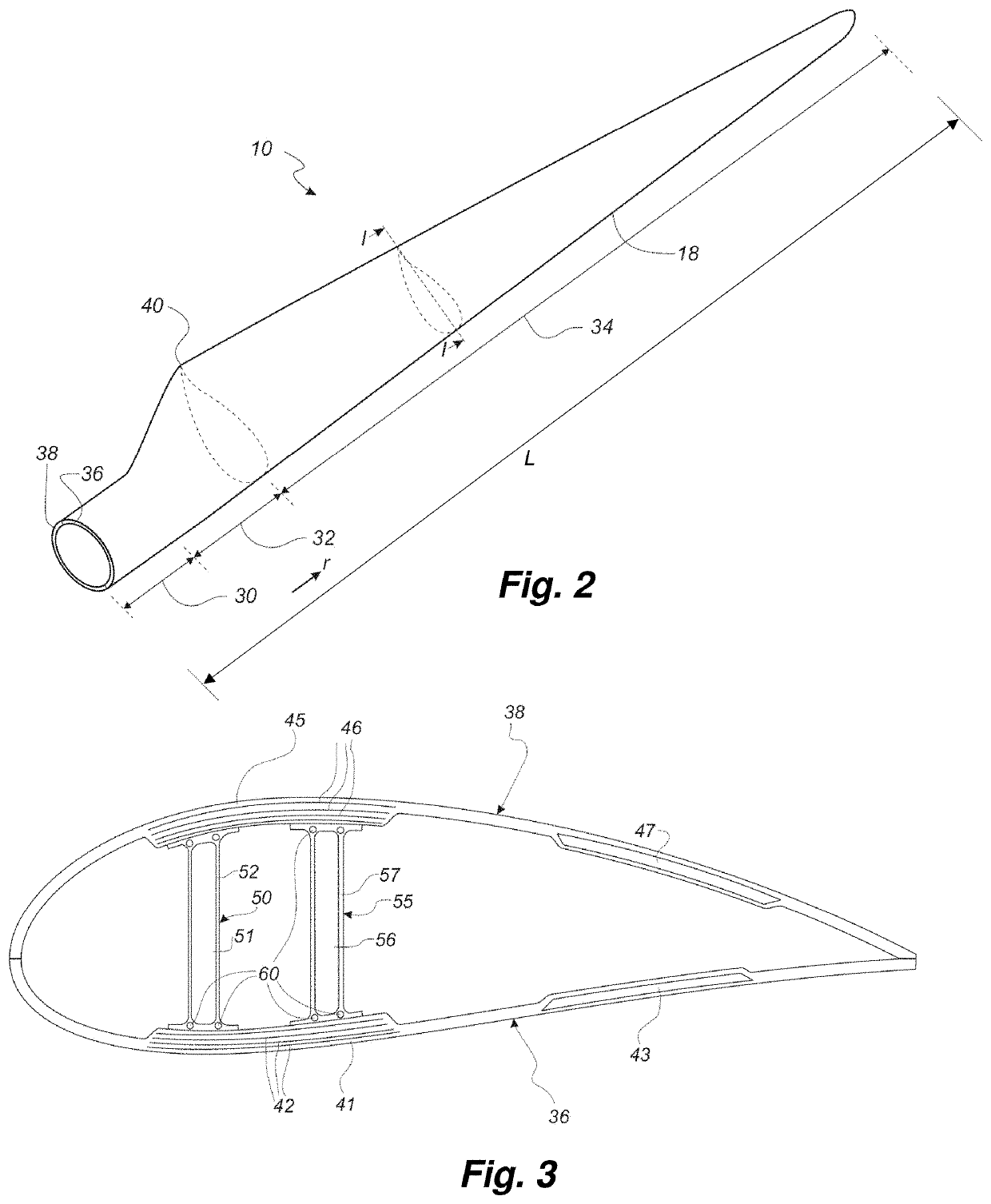
[0061]FIG. 2 shows a schematic view of a wind turbine blade,

[0062]FIG. 3 shows a schematic view of a cross-section of a wind turbine blade,

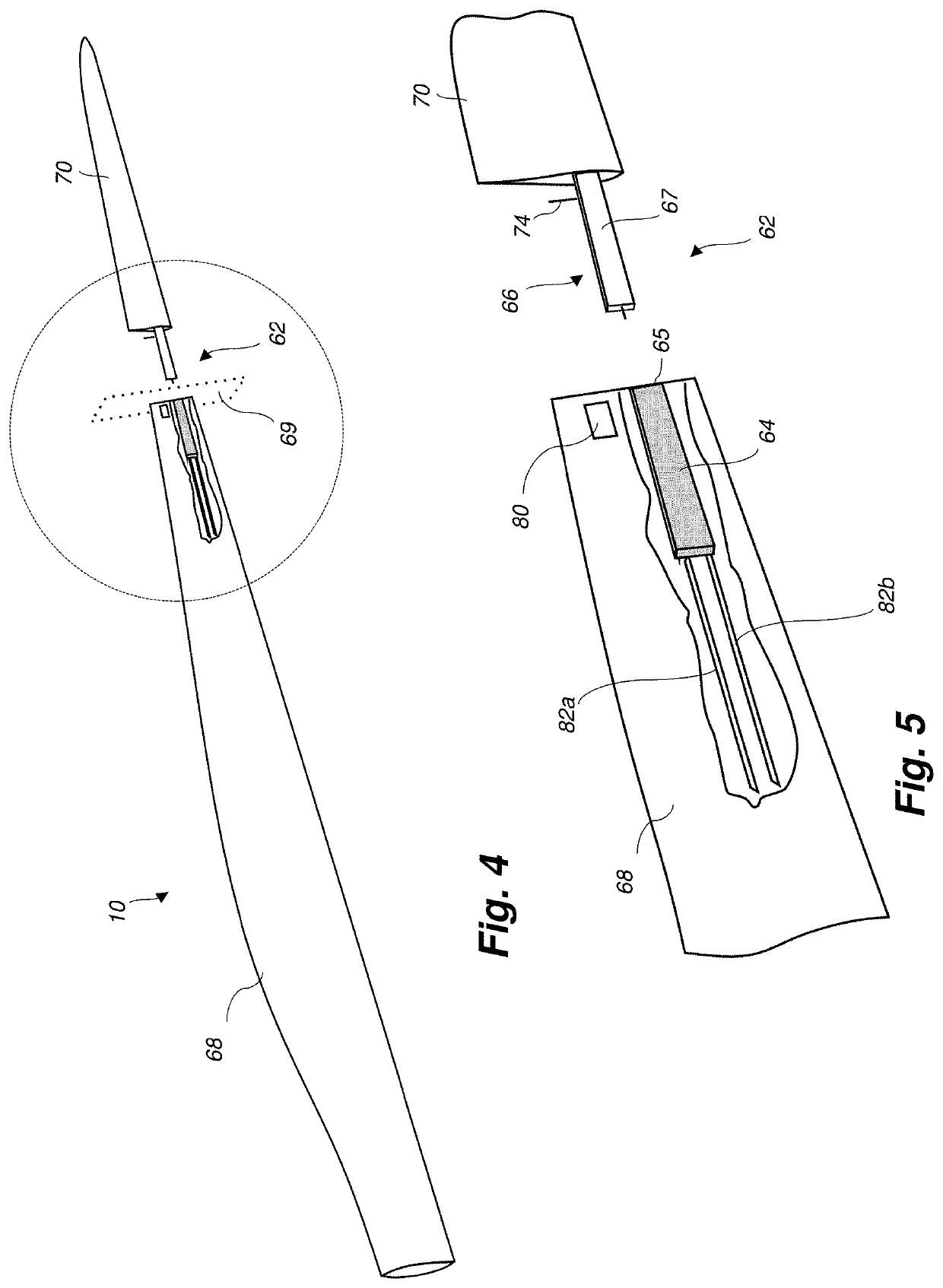
[0063]FIG. 4 is a schematic cut-open view of a wind turbine blade according to the present invention,

[0064]FIG. 5 is an enlarged view of the encircled section in FIG. 4, and

[0065]FIGS. 6, 7 and 8 are perspective views of a spar structure according to the present invention.

DETAILED DESCRIPTION

[0066]FIG. 1 illustrates a conventional modern upwind wind turbine according to the so-called “Danish concept” with a tower 4, a nacelle 6 and a rotor with a substantially horizontal rotor shaft. The rotor includes a hub 8 and three blades 10 extending radially from the hub 8, each having a blade root 16 nearest the hub and a blade tip 14 farthest from the hub 8. The rotor has a radius denoted R.

[0067]FIG. 2 shows a...


PUM


Abstract

The present invention relates to a method of manufacturing a wind turbine blade comprising the steps of manufacturing a pressure shell halves and arranging a spar structure (62) within one of the shell halves. The spar structure (62) comprises two parts releasably coupled to each other. The method results in a segmented wind turbine blade for easy transportation and re-assembly.

Description

FIELD OF THE INVENTION[0001]The present invention relates to a method of manufacturing a wind turbine blade, and to a wind turbine blade obtainable by said method.BACKGROUND OF THE INVENTION[0002]Wind power provides a clean and environmentally friendly source of energy. Wind turbines usually comprise a tower, generator, gearbox, nacelle, and one or more rotor blades. The wind turbine blades capture kinetic energy of wind using known airfoil principles. Modern wind turbines may have rotor blades that exceed 90 meters in length.[0003]Wind turbine blades are usually manufactured by forming two shell parts or shell halves from layers of woven fabric or fibre and resin. Spar caps or main laminates are placed or integrated in the shell halves and may be combined with shear webs or spar beams to form structural support members. Spar caps or main laminates may be joined to, or integrated within, the inside of the suction and pressure halves of the shell.[0004]As the size of wind turbines in...

Claims


Application Information

Patent Timeline
Patent Type & Authority Applications(United States)
IPC IPC(8): F03D1/06F03D80/30F03D80/50
CPCF03D1/0675F03D80/30F05B2260/30F05B2230/10F05B2240/302F03D80/50F05B2230/50F05B2230/60B29D99/0028Y02E10/72Y02P70/50
Inventor ROBERTSJØNSSON, LARS BANGMUKHERJEE, MANISHTODD, PAULHANCOCK, MARK
Owner BLADE DYNAMICS LTD
Why Eureka
Try Eureka