Liquid crystal display having reduced image quality deterioration and an improved viewing angle, and a method of driving the same

a liquid crystal display and image quality technology, applied in non-linear optics, instruments, optics, etc., can solve problems such as deterioration of image quality of display, reduce or prevent rapid changes in transmittance, and improve the viewing angle of display.

Active Publication Date: 2017-01-31
SAMSUNG DISPLAY CO LTD
View PDF49 Cites 1 Cited by
  • Summary
  • Abstract
  • Description
  • Claims
  • Application Information

AI Technical Summary

Benefits of technology

[0006]Exemplary embodiments of the present invention provide a liquid crystal display in which there is little or no change in the transmittance in a predetermined gray level. Exemplary embodiments further provide a liquid crystal display having reduced image quality deterioration, and an improved viewing angle.
[0015]According to exemplary embodiments of the present invention, in a liquid crystal display, the change in transmittance at a predetermined gray level may be smooth, and periods including no change in transmittance or rapid changes in transmittance may be reduced or prevented. For example, deterioration of image quality may be reduced or prevented, and / or the viewing angle of the display may be improved by dividing one pixel into two pixel electrodes, and controlling a ratio of the voltage applied to a second subpixel electrode (e.g., a relatively low voltage) to the voltage applied to a first subpixel electrode (e.g., a relatively high voltage) to about 0.76 to about 0.80, and more specifically, to about 0.77 to about 0.79.

Problems solved by technology

However, this may also result in the transmittance of light being deteriorated in the middle gray level, thus deteriorating image quality of the display.

Method used


Image

  • Liquid crystal display having reduced image quality deterioration and an improved viewing angle, and a method of driving the same
  • Liquid crystal display having reduced image quality deterioration and an improved viewing angle, and a method of driving the same
  • Liquid crystal display having reduced image quality deterioration and an improved viewing angle, and a method of driving the same

Examples


Embodiment Construction

[0025]Exemplary embodiments of the present invention will be described more fully hereinafter with reference to the accompanying drawings. Like reference numerals may refer to like elements throughout the accompanying drawings.

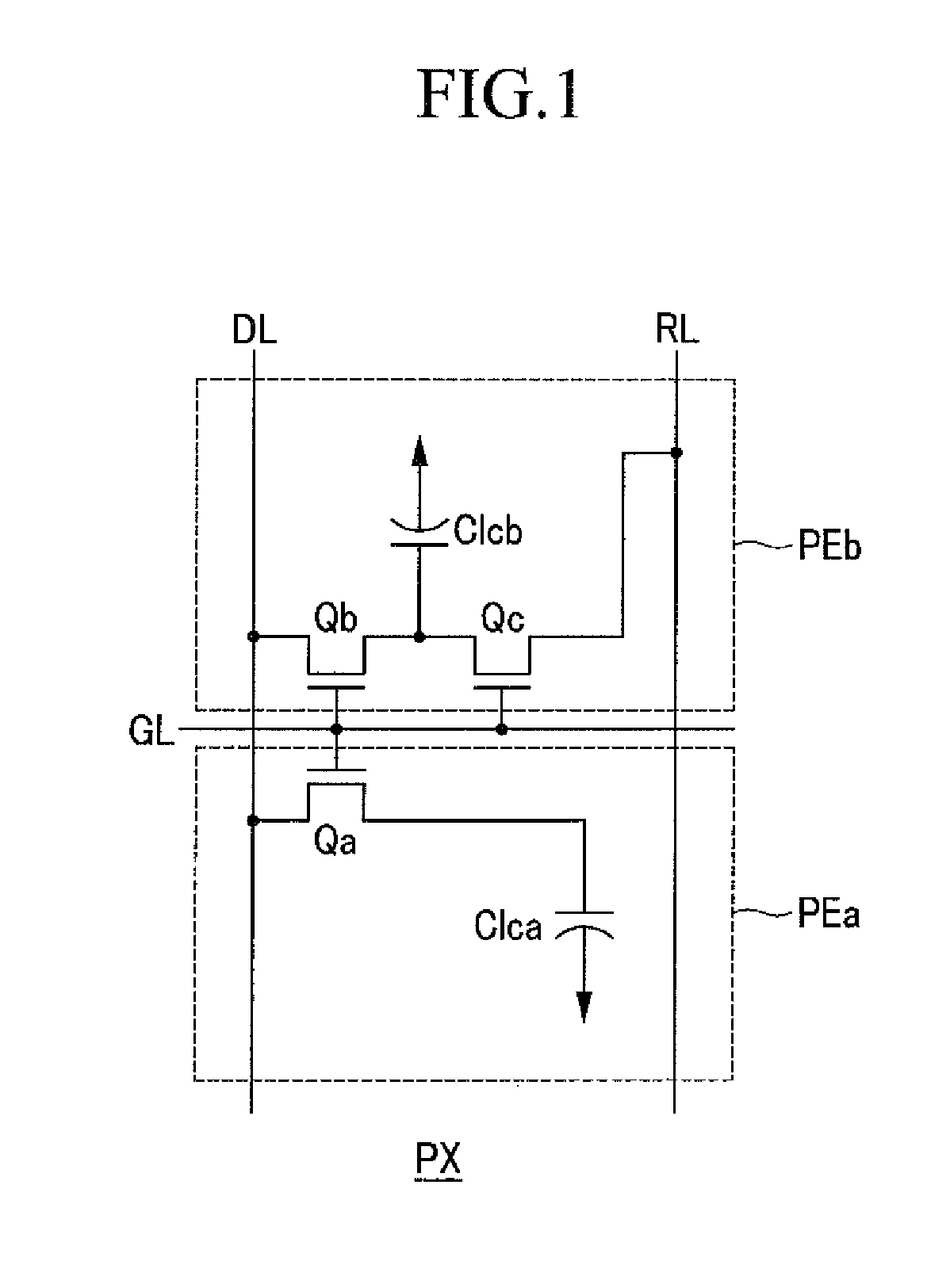
[0026]FIG. 1 is an equivalent circuit diagram for one pixel of a liquid crystal display, according to an exemplary embodiment of the present invention.

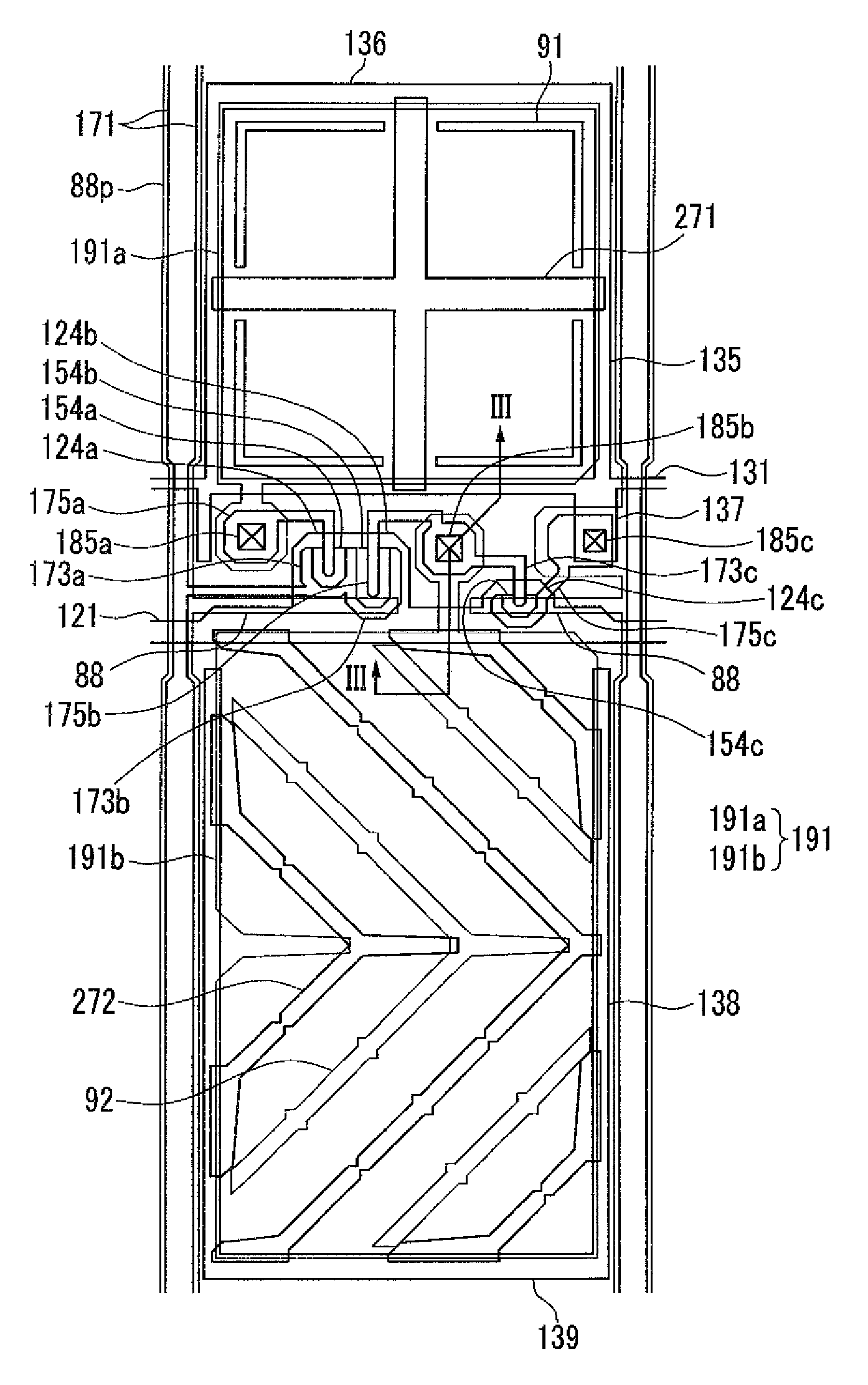
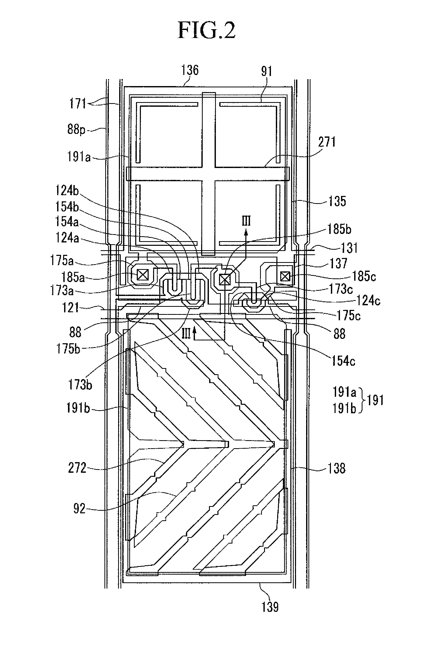
[0027]Referring to FIG. 1, one pixel PX of the liquid crystal display includes a gate line GL through which a gate signal is transferred, a data line DL through which a data signal is transferred, a plurality of signal lines including a reference voltage line RL through which a partial reference voltage is transferred, a first switching element Qa, a second switching element Qb and a third switching element Qc connected to a plurality of signal lines, a first liquid crystal capacitor Clca, and a second liquid crystal capacitor Clcb.

[0028]The first switching element Qa and the second switching element Qb are conn...


PUM

PropertyMeasurementUnit
Daaaaaaaaaaa
voltageaaaaaaaaaa
areasaaaaaaaaaa

Abstract

A liquid crystal display includes a first substrate, a pixel electrode formed on the first substrate, a second substrate facing the first substrate, and a common electrode formed on the second substrate. The pixel electrode includes a first subpixel electrode disposed in a first subpixel region, and a second subpixel electrode disposed in a second subpixel region. A first voltage applied to the first subpixel electrode and a second voltage applied to the second subpixel electrode are different from each other, and a ratio of the first voltage to the second voltage is about 0.76 to about 0.80.

Description

CROSS-REFERENCE TO RELATED APPLICATION[0001]This application claims priority under 35 U.S.C. §119 to Korean Patent Application No. 10-2012-0063087, filed on Jun. 13, 2012, the disclosure of which is incorporated by reference herein in its entirety.TECHNICAL FIELD[0002]The present invention relates to a liquid crystal display, and a method of driving a liquid crystal display.DISCUSSION OF THE RELATED ART[0003]A liquid crystal display typically includes two display panels including field generating electrodes such as a pixel electrode and a common electrode, and a liquid crystal layer interposed therebetween. An electric field is generated in the liquid crystal layer by applying a voltage to the field generating electrodes. The electric field determines the direction of liquid crystal molecules of the liquid crystal layer, and controls polarization of incident light through the generated electric field, thus displaying images.[0004]A vertically aligned (VA) mode liquid crystal display...

Claims


Application Information

Patent Timeline
Patent Type & Authority Patents(United States)
IPC IPC(8): G02F1/1343G02F1/1362G02F1/1337
CPCG02F1/134336G02F1/1337G02F1/13624G02F2001/134345G02F1/134345G02F1/1343
Inventor JUNG, JAE-HOONKIM, HOONSHIN, CHEOLKIM, KA EUNKIM, SU JEONGSHIN, KI CHULOH, HO KILHAN, MIN JUYANG, DAN BIHONG, JI PHYO
Owner SAMSUNG DISPLAY CO LTD
Why Eureka
Try Eureka