[0006]The present invention has been devised to solve the above-described problem, and an object of the present invention is to provide a valve gear of an engine which can properly prevent that the camshaft locks and stops rotating because of the operational malfunction or the like of the operational member.
[0009]According to the present invention, since the cam element portion is configured such that the respective maximum lift portions of the pair of end-face cams are provided at the respective phases which are different from each other in the rotational direction and that the maximum value of the length, in the axial direction, between the respective cam faces of the pair of end-face cams which are provided at the same phase is set to be the arrangement distance, in the axial direction, between the first and second operational members or smaller, that is—since there is not a phase in which the length between the pair of end-face cams provided at the both sides of the cam element portion is greater than the arrangement distance between the first and second operational members, the cam element portion does not get stuck between the first and second operational members. Thereby, the present invention can properly prevent that the camshaft locks and stops rotating.
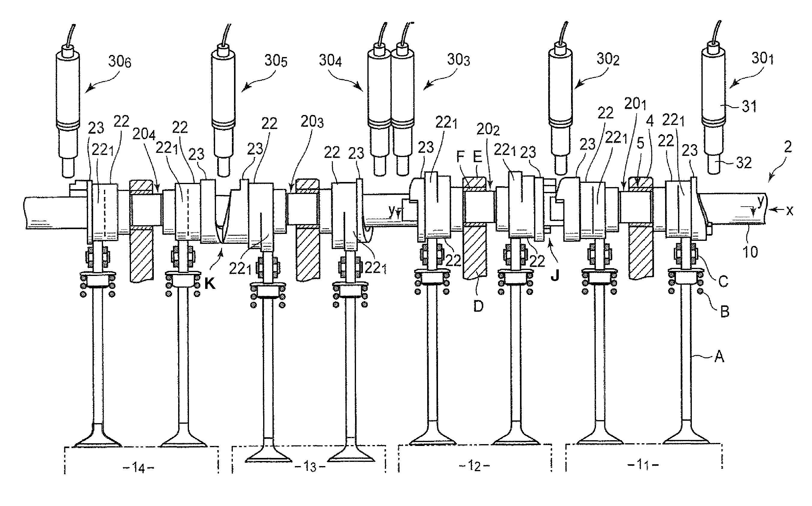
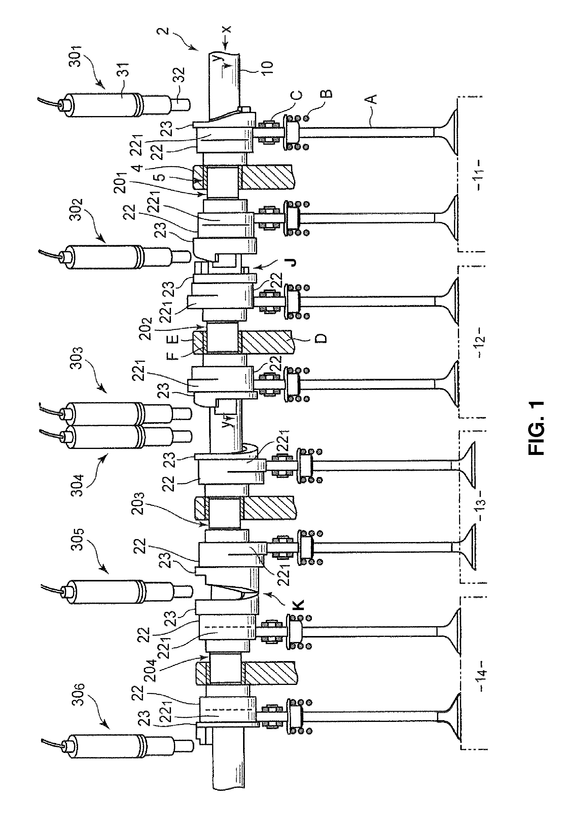
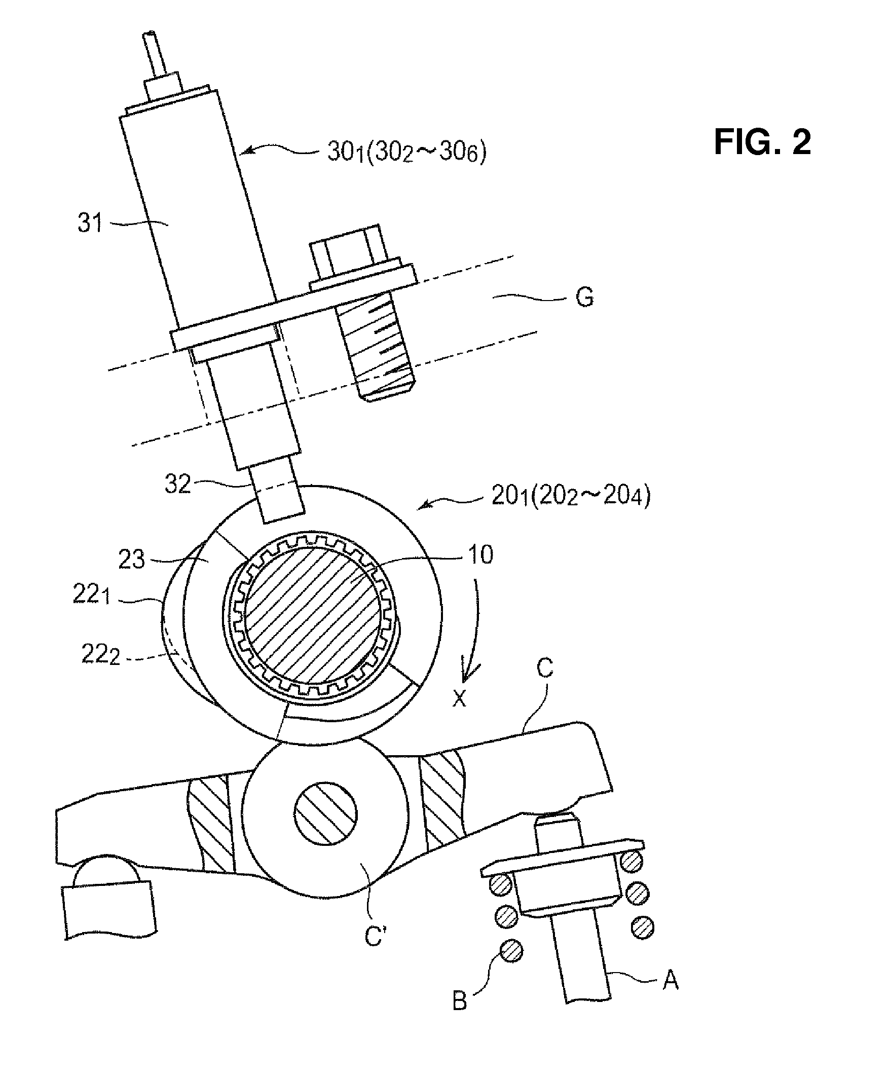
[0011]According to another embodiment of the present invention, the engine is equipped with plural cylinders which are arranged in the axial direction of the shaft portion of the camshaft, the cam element portion is configured as plural cam element portions which are provided for the engine as a whole and at least one of which is provided for each cylinder, at least part of the plural cam element portions includes a pair of cam element portions which are provided for valves of two adjacent cylinders, the pair of cam element portions being configured such that respective lift portions of the end-face cams thereof which face each other are provided at different phases, in the rotational direction, from each other and come to overlap each other in the axial direction at least partially when the pair of cam element portions come close to each other, and the operational device further includes a common operational member of a common operational device, which is configured, in a state in which the pair of cam element portions are in a close state, to project to a position facing the both end-face cams of the pair of cam element portions and contact the both lift portions of the end-face cams so as to move the pair of cam element portions away from each other when being at the operative position thereof. According to this embodiment, since the common operational member taking the operative position which makes the pair of cam element portions move away from each other is provided and also the pair of cam element portions are configured such that respective lift portions of the end-face cams thereof which face each other are provided at different phases, in the rotational direction, from each other and also come to overlap each other in the axial direction at least partially when the pair of cam element portions come close to each other, the valve gear can be made properly compact in the axial direction of the camshaft, so that the engine compactness can be improved.
[0012]Herein, it may be preferable that the above-described common operational member is configured substantially in a cylindrical shape, and the pair of cam element portions are configured such that in the state in which the pair of cam element portions are in the close state, the minimum value of a distance, in the axial direction, between respective cam faces of the facing end-face cams thereof which are provided at the same phase is smaller than the diameter of the common operational member. Thereby, when the pair of cam element portions are in the close state, even if the common operational member projects because of some operational trouble or the like, this common operational member merely hits on a surface of an outer peripheral portion of the above-described respective cam faces of the end-face cams, not contacts the cam faces of the end-face cams. Accordingly, it can be prevented that the cam element portions move unexpectedly and improperly.
[0013]Further, it may be preferable that the pair of cam element portions further comprise, respectively, a slope portion which slants outward toward the rotary-delay side from the maximum-lift portion of the end-face cam which the common operational member contacts, the slope portion being configured to retreat the common operational member to the retreat position from the operative position when sliding on the common operational member after the axial-direction move of the cam element portions caused by the end-face cams is finished. Thereby, the common operational member being at the operative position can be moved to the retreat position surely by the slope portion. Further, since the slope portion is configured to operate (work) after the cam element portion has been moved by the common operational member, the common operational member can be quickly retreated to the retreat position, ensuring the move of the cam element portion. Thereby, even in a case in which the cams are switched continuously, the switching operation of the cam portions can be conducted continuously in a moment.

