Hybrid powertrain for a motor vehicle, hybrid vehicle, and use thereof

a hybrid vehicle and powertrain technology, applied in mechanical equipment, transportation and packaging, gearing, etc., can solve the problems of reducing the number of selectable gear ratios and the disadvantage of the known device axial structural size, and achieve the effect of reducing the number of selectable gear ratios and axial structural siz

Active Publication Date: 2017-02-28
VOLKSWAGEN AG
View PDF12 Cites 3 Cited by
  • Summary
  • Abstract
  • Description
  • Claims
  • Application Information

AI Technical Summary

Benefits of technology

[0011]It is the object of the present invention to further develop a generic drivetrain such that the axial structural size is reduced without a reduction in the number of selectable gear ratios.
[0019]The sun gear of the planetary gear set expediently acts as the input element thereof, and the web of the planetary gear set expediently acts as the output element connected to the electric machine driveshaft, wherein the internal gear of the planetary gear set is expediently arranged so as to be fixed with respect to a housing. The planetary gear set clutch is preferably configured so as to connect the rotor of the electric machine selectively either to the sun gear or to the web. Since, as explained above, the web, as output element of the planetary gear set, is connected to the electric machine driveshaft, the former switching position means that the planetary gear set acts as a simple transmission stage, whereas in the latter switching position, there is a direct torque flow between rotor and electric machine driveshaft.

Problems solved by technology

Furthermore, the internal gear of the planetary gear set is connected to the combustion engine driveshaft, such that the two drive paths are not independent of one another.
Aside from this lack of independency, the considerable axial structural size of the known device is also a disadvantage; this arises substantially from the axial space requirement of the numerous driveshaft pinions arranged axially adjacent to one another.

Method used


Image

  • Hybrid powertrain for a motor vehicle, hybrid vehicle, and use thereof
  • Hybrid powertrain for a motor vehicle, hybrid vehicle, and use thereof
  • Hybrid powertrain for a motor vehicle, hybrid vehicle, and use thereof

Examples


Embodiment Construction

[0034]In the figures, the same reference signs are used to denote identical or analogous elements.

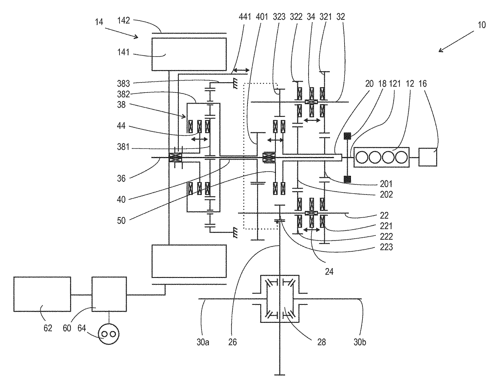
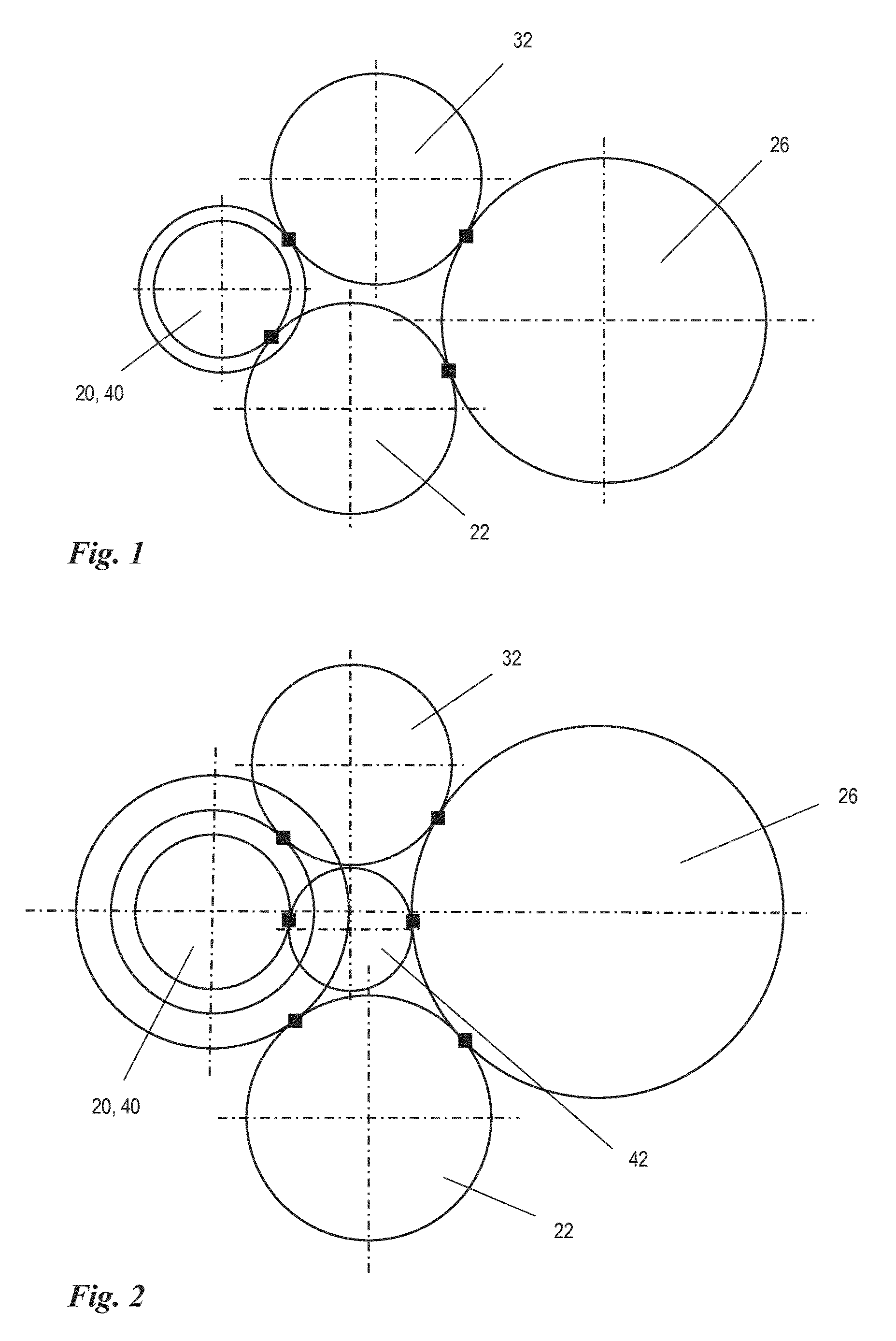
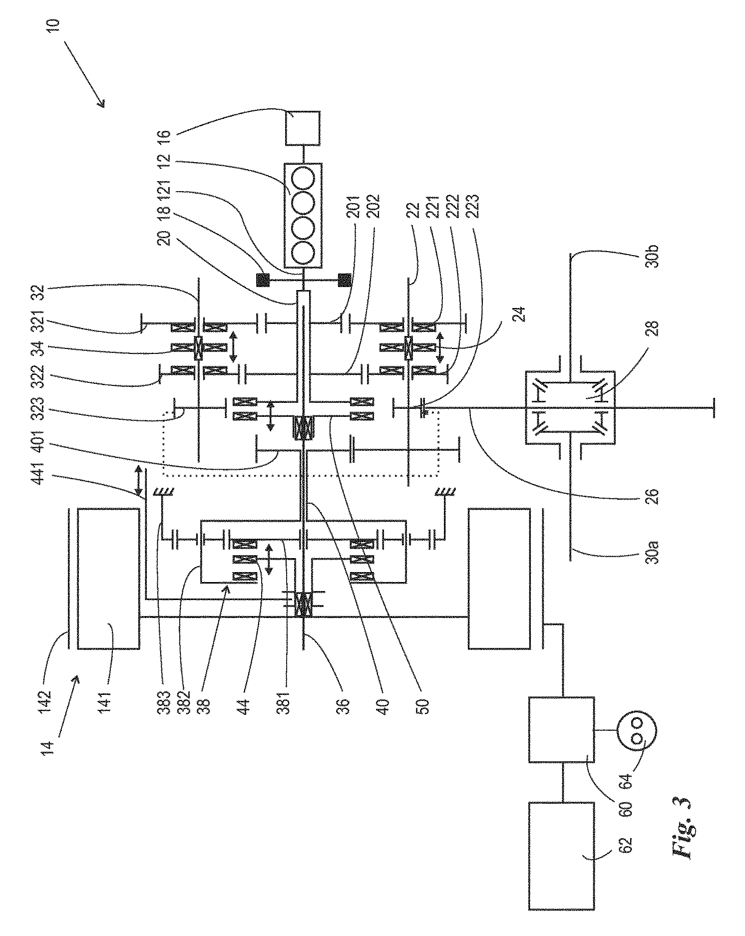
[0035]FIG. 1 is a schematic cross-sectional illustration of an embodiment of the first invention variant, the topology of which is illustrated in the overview sketch in FIG. 3. These two figures will be discussed jointly below. The arrangement shown will hereinafter be referred to, for short, as a 3-shaft arrangement. A drivetrain 10 has two drive units, specifically a combustion engine 12 and an electric machine 14, comprising an internal rotor 141 and an external stator 142. In the embodiment illustrated, the combustion engine 12 is connected to a start / stop unit 16, which is however not of central significance for the present invention. The crankshaft 121 of the combustion engine 12 is coupled, by way of a dual-mass flywheel 18, to a combustion engine driveshaft 20, which in the embodiment shown is in the form of a hollow shaft. The combustion engine driveshaft bears two driveshaft p...


PUM


Abstract

A hybrid powertrain for a motor vehicle has an internal combustion engine and an electric machine that is connected to power electronics and to an electric energy storage device. The internal combustion engine is coupled to an internal combustion engine driveshaft and the rotor of the electric machine is coupled to an electric machine driveshaft that is connected to a planetary gear set with a sun gear, a planet carrier, and a ring gear, one element of which functions as an input element and another as an output element. The rotor of the electric machine can be selectively connected either to the input element or to the output element of the planetary gear set by way of a shiftable clutch).

Description

FIELD OF THE INVENTION[0001]A hybrid drivetrain for a motor vehicle, having a combustion engine and having an electric machine which is connected to power electronics and to an electrical energy store and which has a stator and a rotor, which combustion engine and electric machine are connectable in torque-transmitting fashion to an output shaft, wherein[0002]the combustion engine is coupled to a combustion engine driveshaft which bears one or more driveshaft pinions,[0003]the rotor of the electric machine is coupled to an electric machine driveshaft, which bears one or more driveshaft pinions, via a planetary gear set comprising a sun gear, a web and internal gear, of which one element acts as input element and another element acts as output element of the planetary gear set,[0004]at least one driveshaft pinion of the combustion engine driveshaft forms a switchably torque-transmitting pinion pairing with a corresponding collective shaft pinion of a first collective shaft which is c...

Claims


Application Information

Patent Timeline
Patent Type & Authority Patents(United States)
IPC IPC(8): B60K6/48B60K6/54F16H37/06B60W30/188B60W10/10B60W10/08B60W10/06B60K6/547B60K6/365F16H3/093
CPCB60K6/54B60K6/365B60K6/48B60K6/547B60W10/06B60W10/08B60W10/10B60W20/15B60W30/1886F16H37/065B60K2006/4808B60K2006/4841F16H2003/0931F16H2003/0933F16H2200/0034F16H2200/0043F16H2200/2005Y02T10/626Y02T10/6221Y10S903/91Y02T10/62
Inventor LUEHRS, GEORG-FRIEDRICHZEISE, DIRK
Owner VOLKSWAGEN AG
Why Eureka
Try Eureka