Imaging polarimetry

An imaging and polarization technology, applied in chipless transponders, information reading at high temperature, and the system field that implements this method, can solve the problems of difficult radar system boundaries or classifications, and achieve simple and reliable identification and classification, high data capacity, avoiding the effects of wave switching

Pending Publication Date: 2018-07-31
SYMEO
View PDF16 Cites 0 Cited by
  • Summary
  • Abstract
  • Description
  • Claims
  • Application Information

AI Technical Summary

Problems solved by technology

These demarcations or subclasses would be significantly more difficult to visualize

Method used


Image

  • Imaging polarimetry
  • Imaging polarimetry
  • Imaging polarimetry

Examples


Embodiment Construction

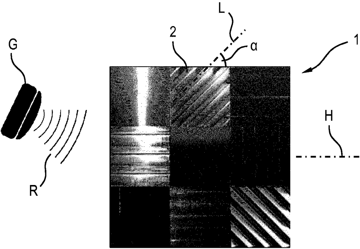
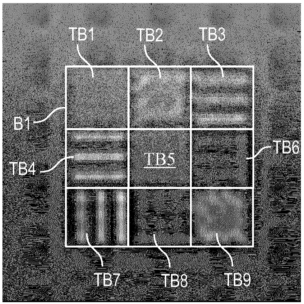
[0059] figure 1 A transponder 1 is shown which is designed as a sheet-shaped aluminum part with a square contour in plan view. The side length can be, for example, approximately 10 cm. The transponder 1 can be illuminated with fully polarized radio waves, in particular radar radiation R, by means of a reading device G. The reflected or backscattered radiation at the transponder 1 can be detected by the reading device G and evaluated there or in a separate evaluation device (above). In particular at least one image B1 to B3 can be produced by means of the detected backscattered radiation (see for example Figure 3 to Figure 5 ), whose image points carry polarization information.

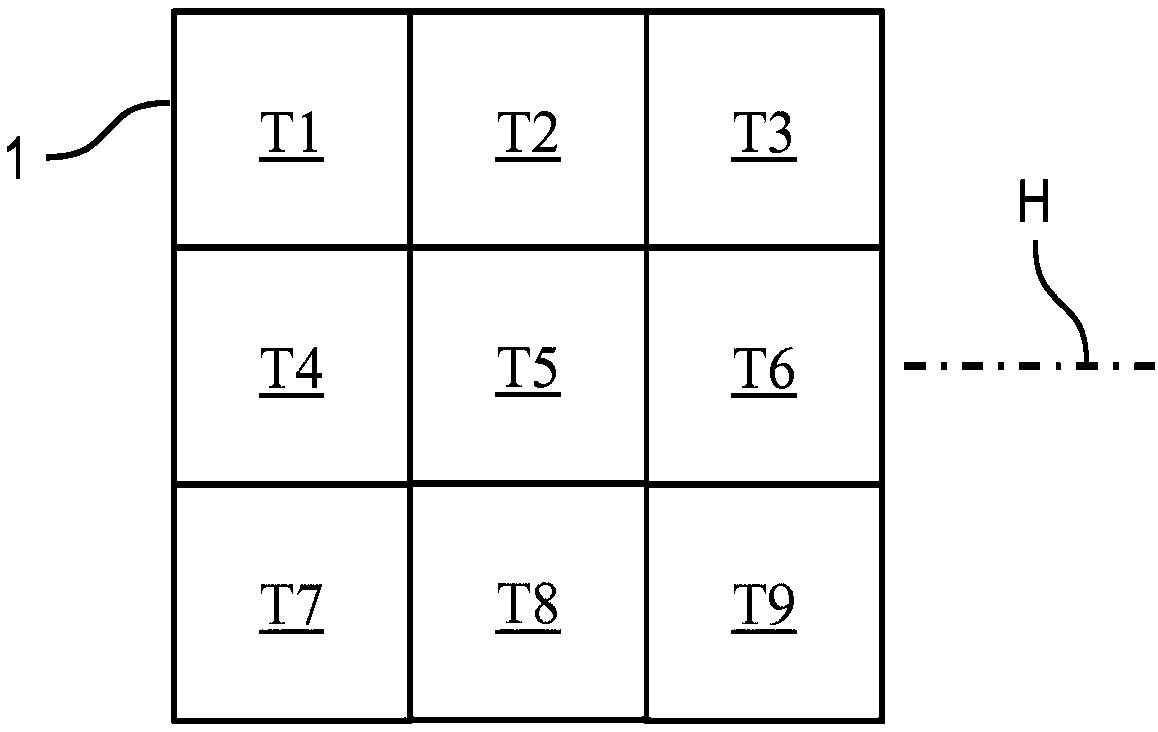
[0060] figure 2 A simplified view of the new fields or partial areas T1 to T9 of the transponder 1 is shown. The partial areas T1 to T9 likewise have a square shape and are of the same size.

[0061] The polarization behavior of the subsurfaces T1 to T9 can be distinguished by means of the meas...


PUM


Abstract

The invention relates to a method which serves for imaging polarimetry, wherein a chipless, passive transponder (1) which has a plurality of surface regions (T1-T9) having different polarimetric properties is illuminated fully polarimetrically by radar radiation (R), at least one polarization-encoded image (B1-B3) of the transponder (1) is generated using the radar radiation (R) reflected thereby,and the different surface regions (T1-T9) of the transponder (1) in the polarization-encoded image (B1-B3) can be recognized by their at least one polarimetric property. A passive, chipless transponder (1) has at least two surface regions (T1-T9) having different polarimetric structures (2, [alpha]).

Description

technical field [0001] The invention relates to a method for imaging polarimetry, in which a chipless, passive transponder or "tag" comprising a plurality of partial areas with different polarization properties is used, and in which, At least one image of the transponder is generated from the radar radiation reflected by it. Furthermore, the invention relates to a passive, chipless transponder. Furthermore, the invention relates to a system for carrying out the method, which system has at least one reading device and at least one transponder. The present invention can be applied, for example, to information reading at high temperatures. Background technique [0002] RFID (“Radio Frequency Identification”) systems with a reading device or interrogation device and a transponder to be interrogated are used in various applications. Here, transponders (also called "RFID-Tags") can in principle be divided into active, semi-passive and passive systems according to their structur...

Claims


Application Information

Patent Timeline
IPC IPC(8): G01S13/75G01S7/02H01Q15/24G01K5/62G01S13/89
CPCG01S13/751G01S13/89H01Q15/248G01S7/024H01Q1/2208
Inventor 马丁·福西克朱利安·奥道迈茨马克西米利安·波佩尔
Owner SYMEO
Why Eureka
Try Eureka