

Rolling component and manufacturing method thereof
A technology of rolling parts and rolling elements, which is applied in the direction of anti-centrifugal force rotating parts, manufacturing tools, bearing components, etc., can solve the problems of large alloy components, damage to economic versatility, increase the cost of JISSUJ2 materials, etc., and achieve suppression of deformation or damage , prolong life, improve the effect of material strength
Inactive Publication Date: 2011-02-09
JTEKT CORP
View PDF2 Cites 11 Cited by
- Summary
- Abstract
- Description
- Claims
- Application Information
AI Technical Summary
Problems solved by technology
[0007] However, among these measures, the amount of alloy components of the steel is too much, which increases the material cost of JIS SUJ2, which causes a problem of impairing economic versatility
Method used
View moreImage
Smart ImageViewing Examples

Examples
Embodiment 1
[0081] In this embodiment, an embodiment of a rolling member and its manufacturing method according to the present invention will be described.
Login to View More PUM
| Property | Measurement | Unit |
|---|---|---|
| particle size | aaaaa | aaaaa |
| particle diameter | aaaaa | aaaaa |
| hardness | aaaaa | aaaaa |
Abstract
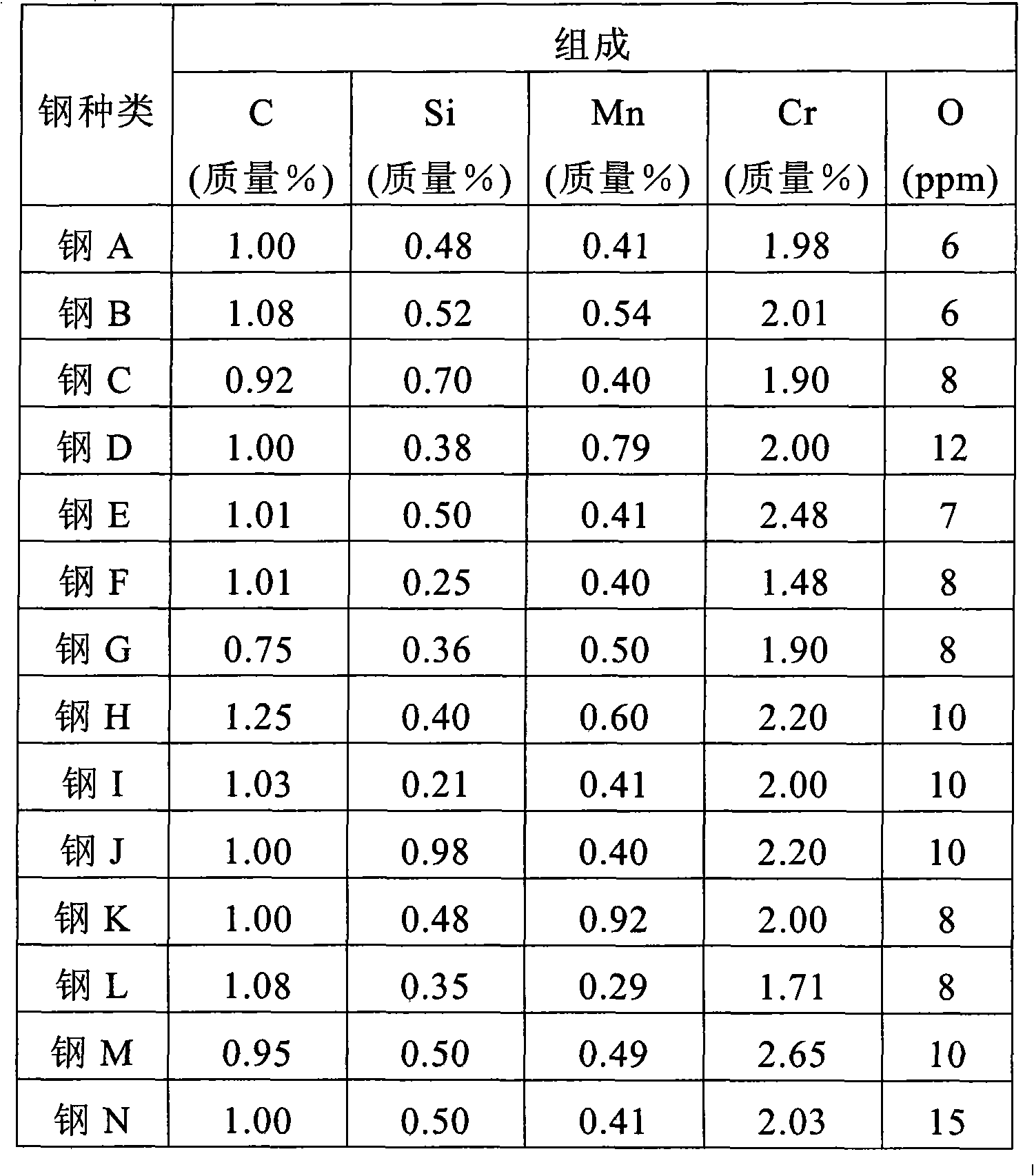
A rolling component formed by carrying out spheroidizing annealing, processing, carbonitriding, and finishing on steel material containing, by mass, 0.90% to 1.10% carbon, more than 0.35% and up to 0.70% silicon, less than 0.80% manganese, 1.85% to 2.50% chromium, and oxygen in the amount of 12 ppm or less. On the surface, the mean quantity of carbon is 1.20% to 1.50% by mass and the mean quantity of nitrogen is 0.10% to 0.60% by mass. There are at least 700,000 deposits with particle diameter of 0.1 [mu]m or more per square millimeter of the surface. Said deposits have a mean particle diameter of 0.6 [mu]m or less and a surface area ratio of 10% or more. The volume fraction of retained austenite on the surface is between 25% and 45%. The surface hardness is Hv 750 or more. The volume fraction of retained austenite inside the rolling component is 20% or less.
Description
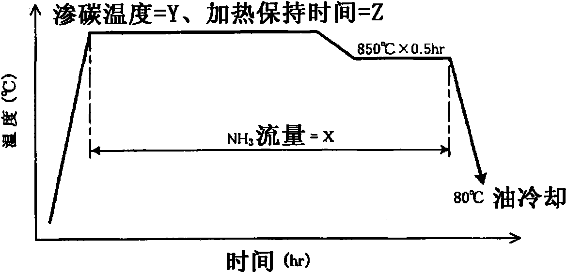
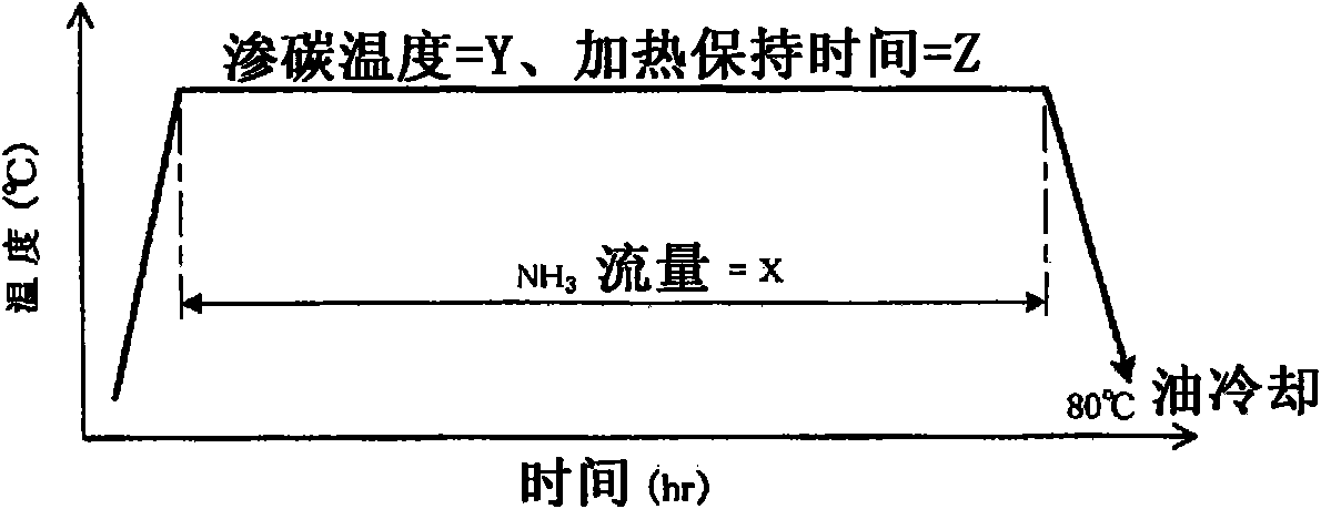
technical field [0001] The present invention relates to a rolling part and a manufacturing method thereof, in particular to a rolling part suitable for use in an impurity-containing lubricating environment and lubricating oil, such as a drive transmission unit for an automobile, and a manufacturing method thereof. [0002] Incidentally, in this specification and claims, the term "rolling member" refers to a member subjected to rolling contact alone or a combination of rolling contact and sliding contact. Background technique [0003] As rolling parts used with lubricating oil containing impurities, for example rolling / sliding parts are known. The rolling / sliding parts are manufactured through a carburizing process, a rapid cooling process, and then an annealing process in which bearing steel (high carbon chromium bearing steel) such as JIS SUJ2 is treated by machining so that It has a predetermined shape to obtain a component raw material, which is heated at 870° C. for 3 h...
Claims
Login to View More Application Information
Patent Timeline
 Patent Type & AuthorityApplications(China)
IPC IPC(8): F16C33/62C21D9/40C22C38/18F16C33/64F16C33/32C21D1/06C22C38/00C23C8/32F16C33/34
CPCF16C2204/66C21D5/00F16C33/30C21D6/002C22C38/02C21D9/40C21D1/32C21D2211/004C22C38/04F16C33/64C23C8/32C22C38/18
Inventor木泽克彦西川友章宇田川毅志
OwnerJTEKT CORP