
Inverter circuit and method for operating the inverter circuit

一种逆变器、电路的技术,应用在用Cuk变换器的变换设备、不可逆的直流功率输入变换为交流功率输出的、电气元件等方向,达到小成本、结构大小减少、部件数量少的效果

Inactive Publication Date: 2011-09-14
SIEMENS AG
View PDF0 Cites 0 Cited by
  • Summary
  • Abstract
  • Description
  • Claims
  • Application Information

AI Technical Summary

Problems solved by technology

However, a disadvantage in this topology is the number of required components, especially electronic switches, since increased switching losses and component costs are associated with this

Method used


Image

  • Inverter circuit and method for operating the inverter circuit
  • Inverter circuit and method for operating the inverter circuit
  • Inverter circuit and method for operating the inverter circuit

Examples


Embodiment Construction

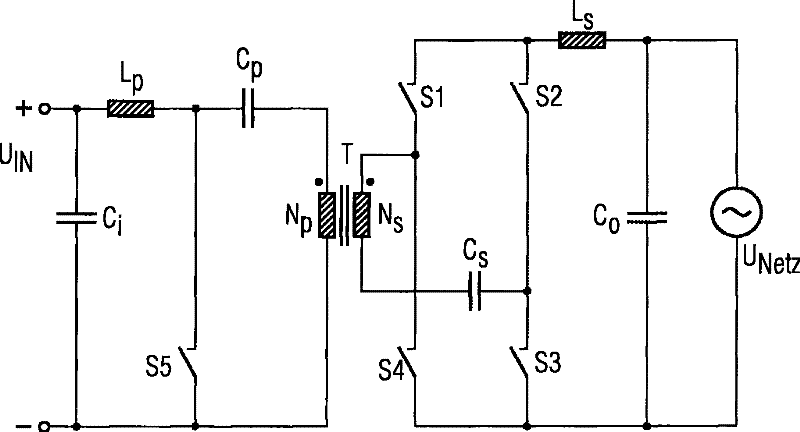
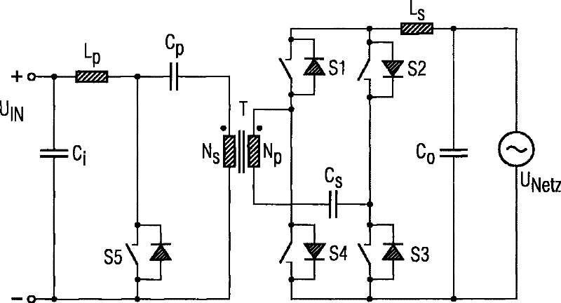
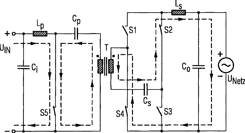
[0056] exist figure 1 The primary stage of a Cuk converter with a transformer T and a secondary stage configured as a full bridge is shown in . The secondary stage includes four switching elements S1, S2, S3 and S4, which are connected in combination as a full bridge. The full bridge will be connected with the first capacitor C s The secondary winding N arranged in series at the transformer T s via the second choke coil L s and output capacitor C o and AC voltage U NETZ connected.

[0057] The primary stage comprises a primary winding N arranged at a transformer T P , which with the second capacitor C P and the first choke L P in series via the input capacitor C i is connected to the DC voltage U IN superior. with primary winding N P and a second capacitor C P The composed series circuit arranges the fifth switching element S5 in parallel.

[0058] Primary and Secondary Windings N P , N S In this case, it is arranged on the transformer T with the same winding d...


PUM


Abstract

The invention relates to an inverter circuit having a primary circuit and a secondary circuit which are galvanically isolated by means of a transformer (T) with the primary circuit having means for clocked connection of a primary winding (NP) to a DC voltage (UIN) which is applied to the input of the inverter circuit, and with the secondary circuit having means for connection of a secondary winding (NS) to an AC voltage (UNETZ) which is produced at the output of the inverter circuit, with the primary circuit furthermore being connected by means of a first inductor (LP) to the DC voltage (UIN), and with the secondary winding (NS) being connected to the AC voltage (UNETZ) by means of a second inductor (CS) in series with a first capacitor, via a full bridge which is formed from four switching elements (S1, S2, S3, S4).

Description

technical field [0001] The invention relates to an inverter circuit comprising a primary circuit and a secondary circuit which are galvanically isolated by means of a transformer, wherein the primary circuit contains means for connecting primary windings in a clocked manner (getakt) means to the DC voltage applied to the input of the inverter circuit, and wherein the secondary circuit contains means for connecting the secondary winding to the AC voltage applied to the output of the inverter circuit. Furthermore, the invention relates to a method for operating an inverter circuit. Background technique [0002] Various inverter circuits with different application possibilities are known from the prior art. Here, various basic types of electronic converters are used, such as boost converters, buck converters, buck-boost converters and combinations thereof. As an example, the publication "Slave converters power auxiliary outputs", Sanjaya Maniktala, in the magazine EDN, 17.10....

Claims


Application Information

Patent Timeline
Patent Type & Authority Patents(China)
IPC IPC(8): H02M7/48H02M7/797H02M7/538H02M7/5395
CPCH02M3/005H02M2001/007H02M7/797H02M7/5395H02M7/4807H02M7/53806H02M1/007H02M7/48H02M7/521
Inventor J·哈拉克
Owner SIEMENS AG
Learn More