Positioning grip for a mobile electronic device

a technology for electronic devices and grips, applied in the direction of manufacturing tools, machine supports, building scaffolds, etc., can solve the problems of reducing the holding force and associated stability, the difficulty of holding an electronic device to an acceptable viewing angle, and the inability to use one or both hands for other activities, etc., to achieve a high-performance, versatile and functional stand

Inactive Publication Date: 2017-02-28
OCTA
View PDF104 Cites 26 Cited by
  • Summary
  • Abstract
  • Description
  • Claims
  • Application Information

AI Technical Summary

Benefits of technology

[0006]It is one aspect of the present invention to provide a multi-functional gripping device that provides an ergonomic and efficient way to hold an electronic device that also functions as a highly versatile and functional stand. Thus, it is one aspect of the present invention to provide a selectively interconnectable grip with an ergonomic and comfortable shape.
[0009]More specifically, it is another aspect of the present invention to provide a grip that transforms into a stand for positioning the electronic device at various viewing angles. Some examples of viewing angles include those normally associated with portrait viewing, portrait typing, landscape viewing, and landscape typing. The flexibility and selective interconnectability of embodiments of the present invention will allow the electronic device to be positioned in many ways. The grip of one embodiment of the present invention also employs a support having flexible positionable arms and / or surfaces that will allow the electronic device to comfortably rest on the user's lap, for example.
[0010]It is another aspect of the present invention to provide a grip that is ergonomic and easy to use. To access stored arms of one embodiment, at least one button is pressed that causes the arms to deploy from the dock. Further, the dock is shaped with curves that correspond to the human hand and that minimizes snag points. Foam over-molded or cushioned material will cover the dock of some embodiments of the present invention which maximizes user comfort. In addition, the positioning grips used in conjunction with some embodiments of the present invention are adapted to rest in a user's hand wherein a stem portion, which extends from a base portion, is placed between the user's fingers or grasped in their fist. In the former example, the base rests comfortably in the user's palm with the stem positioned between two of the user's digits. The base and grip may also be made of a comfortable, spongy, or deformable material that allows for the user to alter the contour thereof to enhance comfort. Still other embodiments of the present invention include a base with a plurality of finger indentations to enhance the user's comfort. Preferably, however, the base is somewhat smooth such that the attached electronic device may be rotated at will with the base “floating” in the user's palm.
[0013]It is another aspect of embodiments of the present invention to provide a positioning grip that allows for secure interconnection to a horizontal or vertical surface. More specifically, one embodiment of the present invention includes a support that is interconnected to the dock. The support also has a mechanism for interconnecting to a horizontal or vertical surface. For example, the support may be connected to a suctioning dock or clamp for interconnection to a horizontal or vertical surface. The support may be in the form of an elongated and selectively-positionable member. This embodiment of the present invention can be used in automobiles, on airplane tray tables, etc. such that one end of the positioning grip is fixed and unable to move relative to the interconnected surface, but the position of the interconnected electronic device can be selectively altered. Other embodiments of the present invention include a support with a bulbous end that interfaces into a cavity of a fixed base that is placed on, or integrated into, a table or wall that allows for selective and operable securement of the support and, thus, the electronic device. The bulbous nature of the support may also provide a swiveling interconnection that allows the electronic device to be moved in three degrees of freedom relative to the fixed interconnection point. The dock may, alternatively, be interconnected to a fixed receiving member that is attached to the back of a car seat, a dash board, a wall, a table, a tripod, a telescoping stand, an articulating stand (as often used in conjunction with lamps), etc.

Problems solved by technology

One drawback of these devices is that their size, shape and / or surface texture often renders them difficult to hold and tilt to an acceptable viewing angle.
Those familiar with such devices will appreciate that after time, the user may become fatigued, which results in the reduction of holding force and associated stability.
Holding an electronic device also does not permit the use of one or both hands for other activities that may be related to the functions being performed by an electronic device, e.g. typing.
Further, some electronic devices are small, sleek, and have smooth surfaces, and are thus difficult to grasp.

Method used


Image

  • Positioning grip for a mobile electronic device
  • Positioning grip for a mobile electronic device
  • Positioning grip for a mobile electronic device

Examples


Embodiment Construction

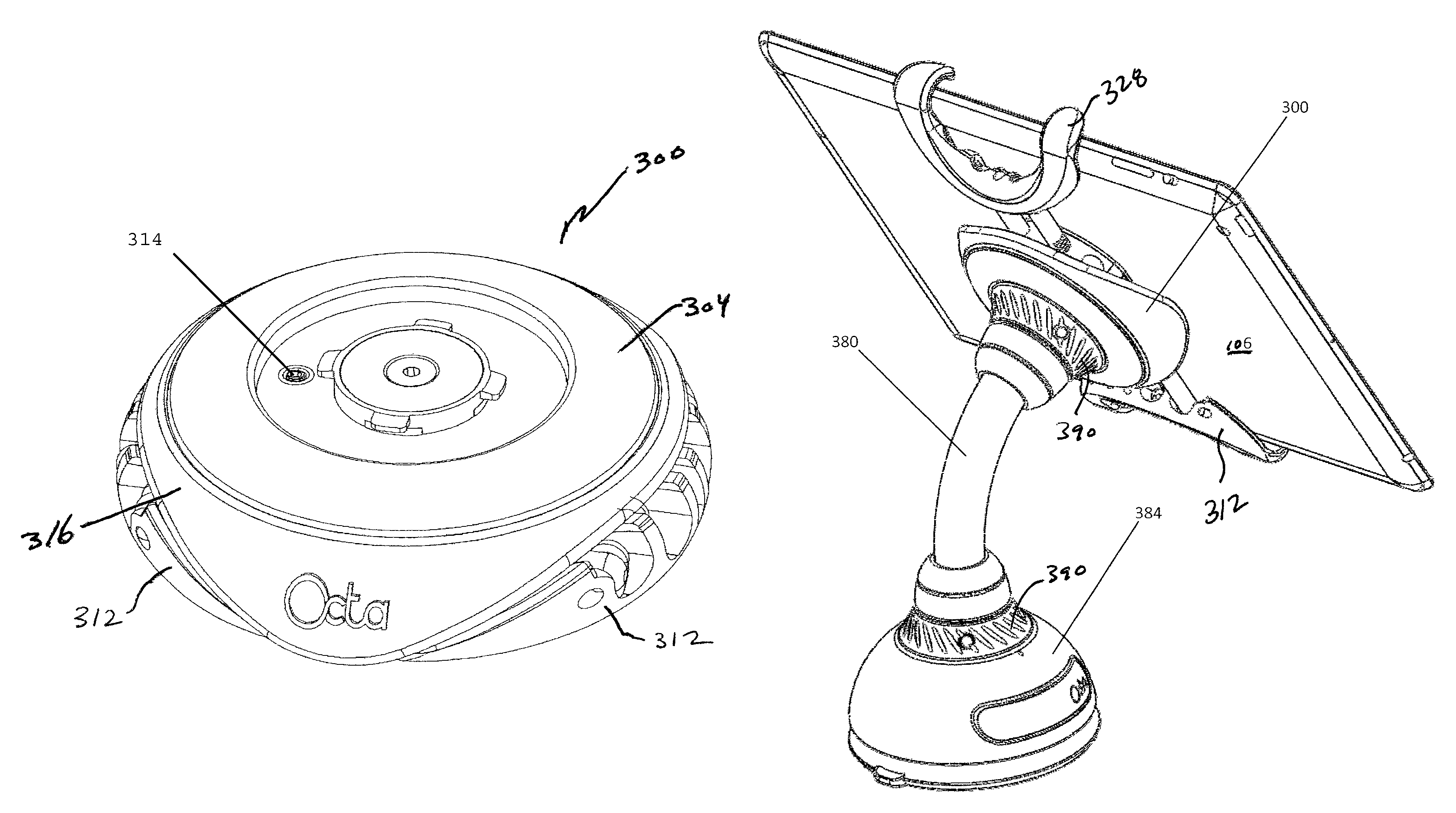
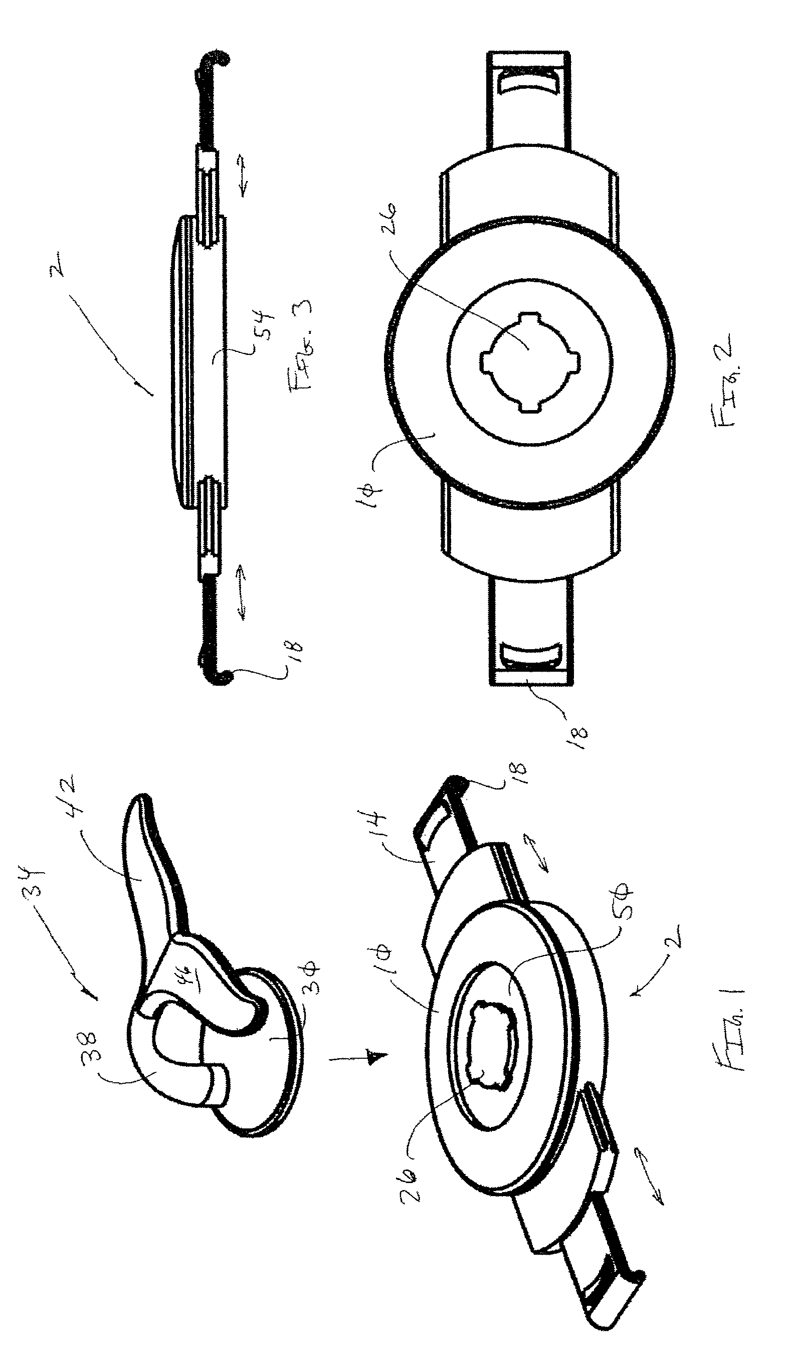
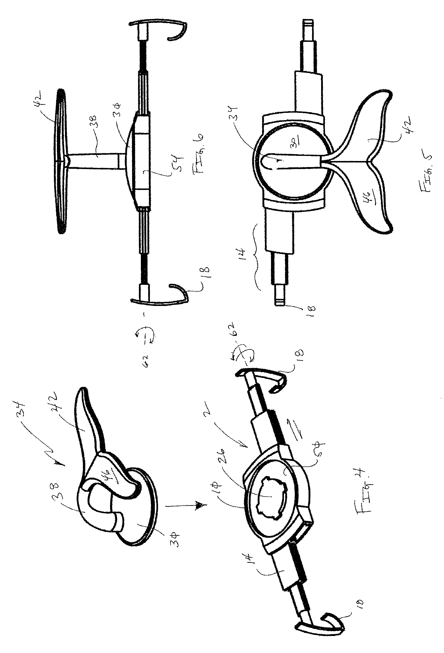
[0081]Referring now to FIGS. 1-25, an electronic device interface 2 is provided that selectively interconnects to an electronic device 6. The electronic device interface 2 is generally comprised of a dock portion 10 with selectively adjustable arms 14. The arms 14 end in fingers 18 that engage edges 22 or corners of the electronic device 6, which secures the electronic device interface 2 to the electronic device 6. To view the electronic device, a user can simply hold the interface. Alternatively, the dock portion 10 includes a fitting 26 that selectively mates with a complimentary fitting of a base portion 30 of a positioning grip 34. The positioning grip 34 further includes a stem 38 that is interconnected to a support 42. One of skill in the art will appreciate that although a bayonet type fitting is shown, other types of selective interconnection systems may be employed without departing from the scope of the invention, such as click lock, magnets, suction, or other selectively ...


PUM

PropertyMeasurementUnit
temperatureaaaaaaaaaa
diameteraaaaaaaaaa
diameteraaaaaaaaaa

Abstract

An electronic device interface is provided that is selectively interconnectable to a portable electronic device. The interface is preferably interconnected to the portable electronic device via inwardly-biased arms that end in fingers that engage opposing edges or corners of the portable electronic device. The interface may receive a positioning grip that includes a support having at least one selectively deflectable surface.

Description

[0001]This application is a Continuation-In-Part of PCT application No. PCT / US2011 / 045921, filed with the WIPO on Jul. 29, 2011, which designates the United States, and which claims the benefit of U.S. Provisional Patent Application Ser. No. 61 / 503,240, filed Jun. 30, 2011, U.S. Provisional Patent Application Ser. No. 61 / 424,973, filed Dec. 20, 2010, U.S. Provisional Patent Application Ser. No. 61 / 400,520, filed Jul. 29, 2010, and U.S. Provisional Patent Application Ser. No. 61 / 414,747, filed Nov. 17, 2010, the entire disclosures of which are incorporated by reference herein.[0002]This application also claims the benefit of U.S. Provisional Patent Application Ser. No. 61 / 709,321, filed Oct. 3, 2012, the entire disclosure of which is incorporated by reference herein.FIELD OF THE INVENTION[0003]Embodiments of the present invention generally relate to a device for selective interconnection to a mobile electronic device to enhance the use thereof. More specifically, one embodiment of th...

Claims


Application Information

Patent Timeline
Patent Type & Authority Patents(United States)
IPC IPC(8): F16M11/10F16M13/02F16M11/04F16M13/04F16M11/40F16M13/00
CPCF16M13/022F16M11/041F16M11/10F16M11/105F16M11/40F16M13/00F16M13/04F16M2200/028Y10T29/49826
Inventor TROTSKY, KEVIN
Owner OCTA
Why Eureka
Try Eureka