
Pad assembly

Active Publication Date: 2017-02-28
NAGAHARA KANICHI
View PDF19 Cites 6 Cited by
  • Summary
  • Abstract
  • Description
  • Claims
  • Application Information

AI Technical Summary

Benefits of technology

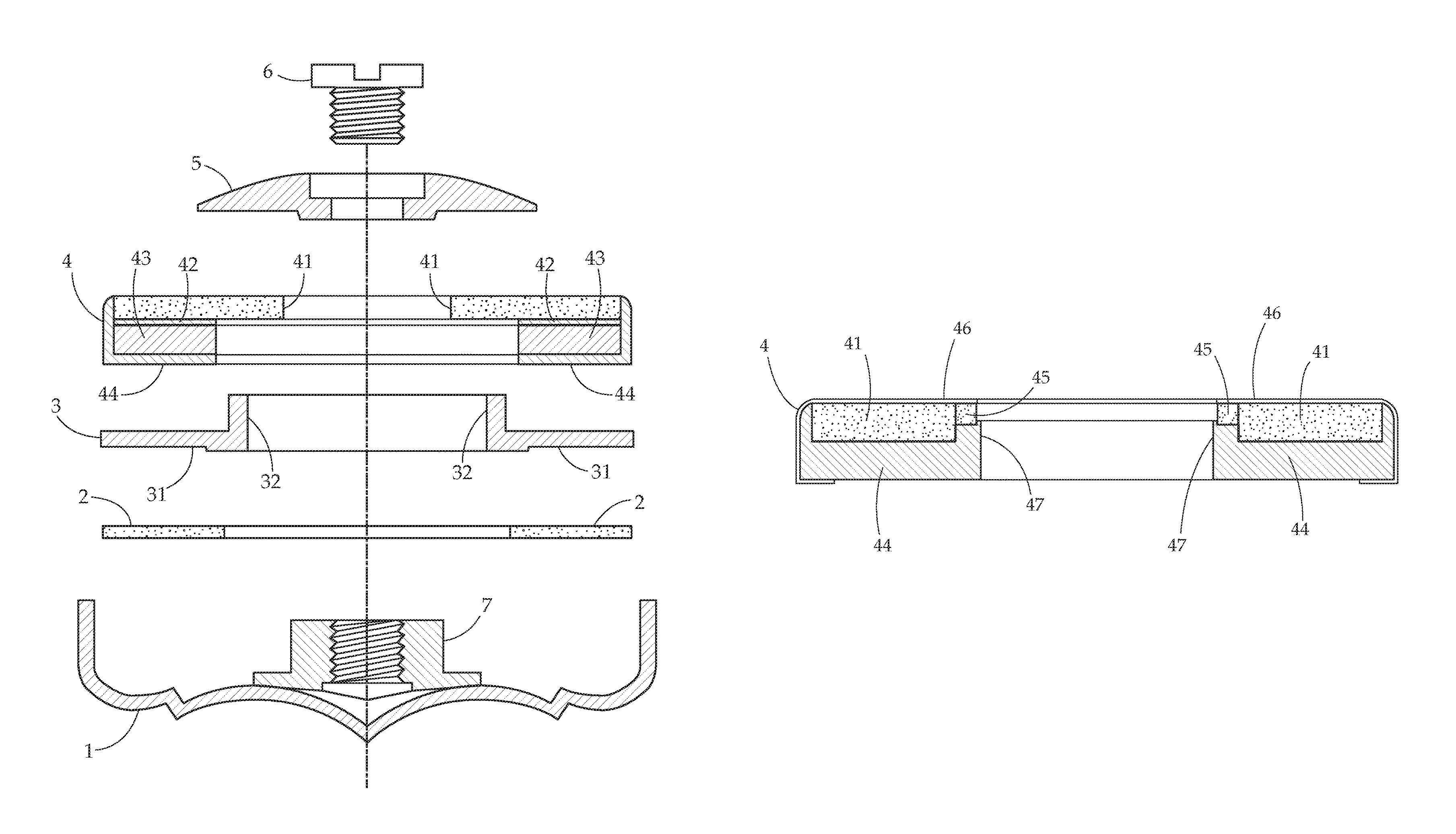
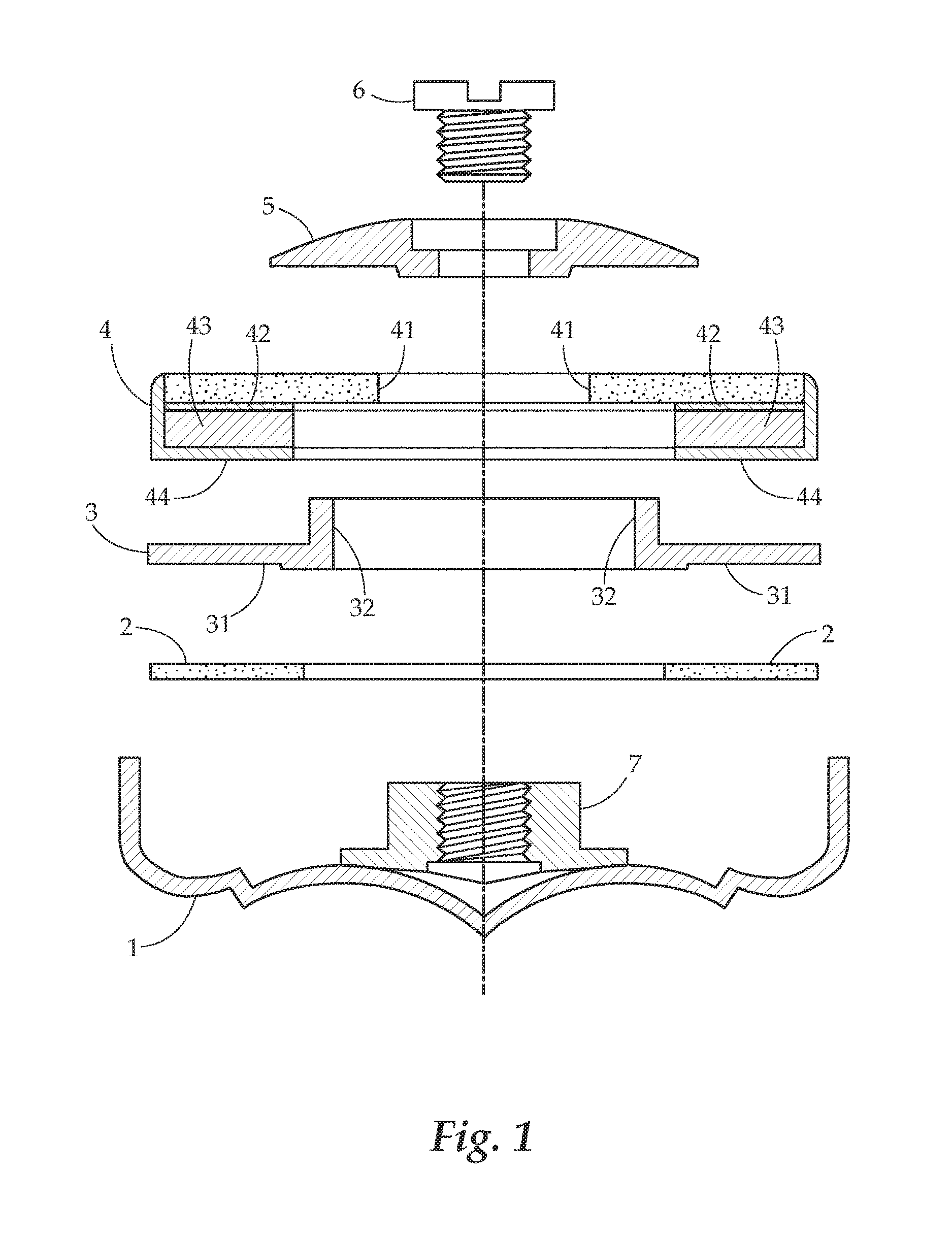
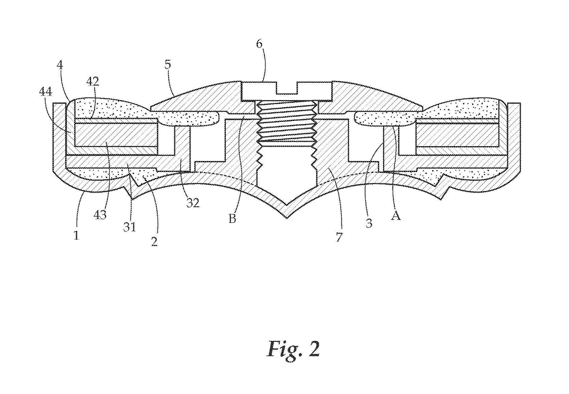
The patent describes a pad assembly for a woodwind instrument. The assembly includes a base that attaches to the instrument key assembly, as well as a pad retainer and a pad positioned above it. Each component has a rounded top-view cross section with an approximately circular central opening. A chimney is formed as an upward protrusion that extends about the inner circumference of the base or pad retainer towards the pad. A ring insert with a different thickness and hardness than the pad is positioned on the top of the chimney. This design prevents contact between the washer and spud, which may improve the overall performance of the instrument.

Problems solved by technology

The size of the tone holes on the modern flute necessitate the use of a cup and pad arrangement, the tone holes being too large and numerous to be closed with only 10 comparatively small human fingers.
The factors that the current invention addresses are cups that are out of alignment with the tone hole due to bending or warpage and / or improperly installed spuds. flute makers do their best to minimize these factors, but it does happen, and indeed flutes can be damaged once out of the makers control, necessitating repair outside the makers shop by repairmen who may not be as skilled as the original maker.
A warped cup is detrimental to the pad's orientation to the tone hole in that the cup is designed to hold the pad at a certain angle and plane.
Spuds are typically soldered into place inside the cup, but if too little solder is used, the spud may not properly seat against the cup.
Conversely, if too much solder is used, the spud may float out of its optimum orientation.
In the first case, if the spud is not installed correctly, the washer will conform to the incorrect spud, and exert pressure on the pad unevenly, thus deforming it and preventing it from performing its function properly.
In the second case, if the flanged bushing is not installed using even, steady pressure, it can be out of alignment with the pad, and result in a similar situation to the first case.

Method used


Image

  • Pad assembly
  • Pad assembly
  • Pad assembly

Examples


Embodiment Construction

[0019]The detailed description set forth below in connection with the appended drawings is intended as a description of presently preferred embodiments of the invention and does not represent the only forms in which the present invention may be constructed and / or utilized. The description sets forth the functions and the sequence of steps for constructing and operating the invention in connection with the illustrated embodiments.

[0020]This invention relates to the field of woodwind musical instruments, such as a flute. Generally, the present invention concerns a sealing pad assembly for closing a wind instrument's tone hole, as well as a device for containing and securing the pad assembly. The pad may be formed as a soft material to provide an air tight seal of the instrument's tone hole. The assembly comprises additional supporting components that minimize deformation of the pad surface and deter tearing which can occur during performance of the instrument. Importantly, the present...


PUM


Abstract

A pad assembly for a flute or other woodwind instrument is provided. The pad assembly may have an upwardly protruding chimney on either a pad base or integral to the pad itself. The pad assembly may be held in place by a washer and screw that is screwed into a spud of a cup, which moves to open and close a tone hole. The upwardly protruding chimney causes compression between the pad and washer, and prevents the washer from directly contacting the spud by creating a spacing between washer and spud. Such a configuration allows the pad assembly to remain in a correct orientation if the cup and a tone hole are misaligned.

Description

BACKGROUND OF THE INVENTION[0001]Field of the Invention[0002]The present invention relates generally to pad assemblies for woodwind instruments. More particularly the present invention relates to a pad assembly that allows a tone hole-sealing pad to be optimally oriented on the tone hole even if the pad cup or cup retaining assembly is deformed or imperfectly installed.[0003]Description of Related Art[0004]The size of the tone holes on the modern flute necessitate the use of a cup and pad arrangement, the tone holes being too large and numerous to be closed with only 10 comparatively small human fingers. On a modern professional-level flute, there are three types of pad and cup arrangements, type 1 being a “spud and washer” design, whereby the pad is secured into the cup by means of a screw, which, when inserted into its threaded receiver (or “spud”), then tightens a washer on top of the pad, which holds it in its respective cup. The second type of arrangement may be described “bush...

Claims


Application Information

Patent Timeline
IPC IPC(8): G10D9/04
CPCG10D9/043G10D7/026G10D9/047
Inventor NAGAHARA, KANICHI
Owner NAGAHARA KANICHI
Learn More