Keyboard device of electronic musical instrument

a technology of electronic musical instruments and keyboards, which is applied in the direction of strings of musical instruments, instruments, electrophonic musical instruments, etc., can solve the problems of difficult to push the retaining hole, unfavorable workability, and complicated work required in the direction of retaining the support shaft, etc., and achieve the effect of correct installation and simple operation of pressing the key

Active Publication Date: 2017-02-28
ROLAND CORP
View PDF13 Cites 3 Cited by
  • Summary
  • Abstract
  • Description
  • Claims
  • Application Information

AI Technical Summary

Benefits of technology

[0012]According to the keyboard device of the electronic musical instrument of a technical solution of the invention, the following effects are achieved. A key is disposed rotatably on a chassis. A rotation center of the key is set as the rear and the key extends from the rear to the front. A support shaft is disposed on the chassis in front of the rotation center of the key. A hammer is disposed rotatably around the support shaft to rotate in conjunction with the key along with pressing on the front of the key. A retaining hole is formed in the hammer for retaining the support shaft such that the hammer is rotatable, and a guide groove is formed by cutting open the retaining hole on the rear. Here, it is a temporarily secured state where the support shaft is temporarily secured in the guide groove of the retaining hole. A shifting means is provided for shifting from the temporarily secured state to a retained state where the support shaft is retained in the retaining hole. That is, the shifting means presses the hammer in the temporarily secured state toward the rear to shift the hammer to the retained state along with the pressing on the front of the key.
[0013]Therefore, for example, if the key is installed and then pressed after the hammer is temporarily secured, the hammer can be shifted to the retained state so as to install the hammer correctly. Accordingly, the hammer can be correctly installed by a simple operation of pressing the key without using a special jig for retaining the support shaft in the retaining hole.
[0014]According to the keyboard device of an electronic musical instrument of another technical solution of the invention, in addition to the aforementioned effects, the following effects are achieved. A protrusion protrudes from the key toward the hammer. A first contact part is formed on a side surface of the rear of the protrusion to be in contact with the hammer in the temporarily secured state. A first contacted part is formed on the hammer to be in contact with the first contact part of the protrusion. At least one of the first contact part of the protrusion and the first contacted part of the hammer is inclined downward from the rear to the front.
[0015]Therefore, if the key is pressed when the hammer is in the temporarily secured state, the first contact part of the protrusion slides obliquely downward from the rear to the front along the first contacted part of the hammer and the first contacted part of the hammer is pressed obliquely downward from the front to the rear by the first contact part of the protrusion (in a direction intersecting the sliding direction of the first contact part of the protrusion). In this case, since at least one of the first contact part of the protrusion and the first contacted part of the hammer is inclined downward from the rear to the front, the direction of the force that the first contact part of the protrusion applies on the first contacted part of the hammer can be changed to a rearward component in the horizontal direction and a downward component in the vertical direction. Accordingly, the support shaft temporarily secured in the guide groove can be pushed into the retaining hole by the rearward component in the horizontal direction to shift the hammer in the temporarily secured state to the retained state.
[0016]Moreover, the key is regarded as a “lever” and the “principle of leverage” is utilized with the rotation center of the key as the fulcrum, the front of the pressed key as the force point, and the portion where the first contact part of the protrusion presses the first contacted part of the hammer as the action point. Thus, the hammer can be shifted from the temporarily secured state to the retained state by a small force.
[0017]According to the keyboard device of an electronic musical instrument of another technical solution of the invention, in addition to the aforementioned effects, the following effects are achieved. The first contact part of the protrusion and the first contacted part of the hammer are separated from each other when the hammer is in the retained state. Therefore, the first contacted part of the hammer is not pressed by the first contact part of the protrusion even if the key is pressed when the hammer is in the retained state. Accordingly, the hammer in the retained state can be rotated smoothly in conjunction with the key, independently of the first contact part of the protrusion and the first contacted part of the hammer.

Problems solved by technology

However, it is a problem that complicated work is required in order to retain the support shaft 28 in the retaining hole 30a through the guide groove 30b, as described in the above Patent Literature 1.
However, on both sides of the hammer 3, the keyboard chassis 1 is set upright with a slight gap between the keyboard chassis 1 and the hammer 3, which is unfavorable for workability and makes it difficult to push the retaining hole 30a to the support shaft 28.
The inevitable complicated work is a problem.

Method used


Image

  • Keyboard device of electronic musical instrument
  • Keyboard device of electronic musical instrument
  • Keyboard device of electronic musical instrument

Examples


first embodiment

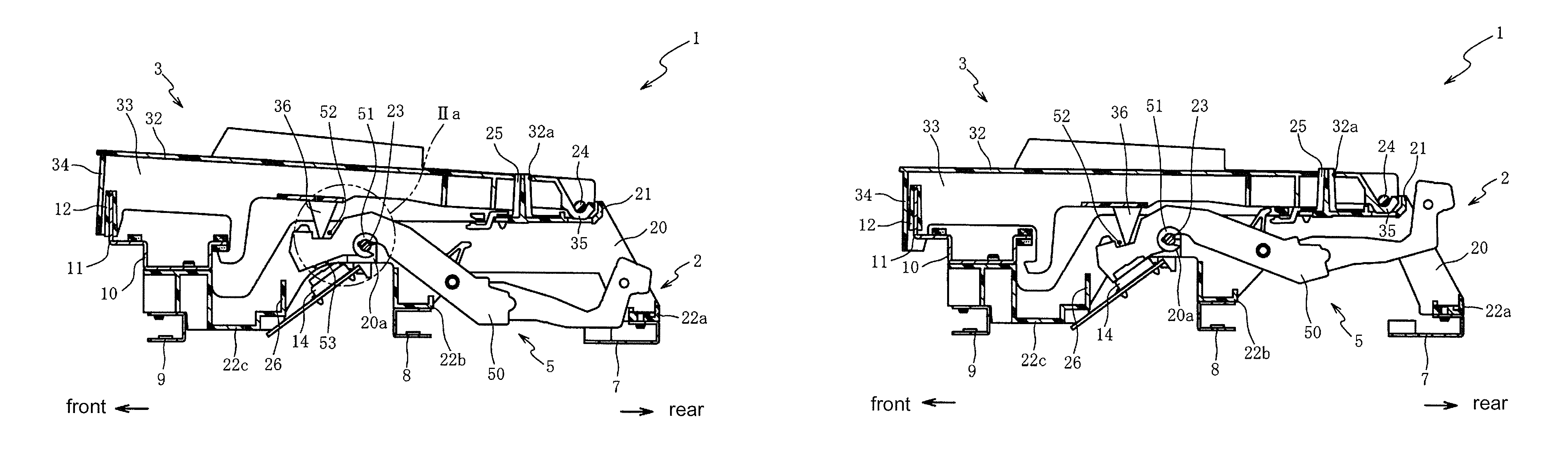
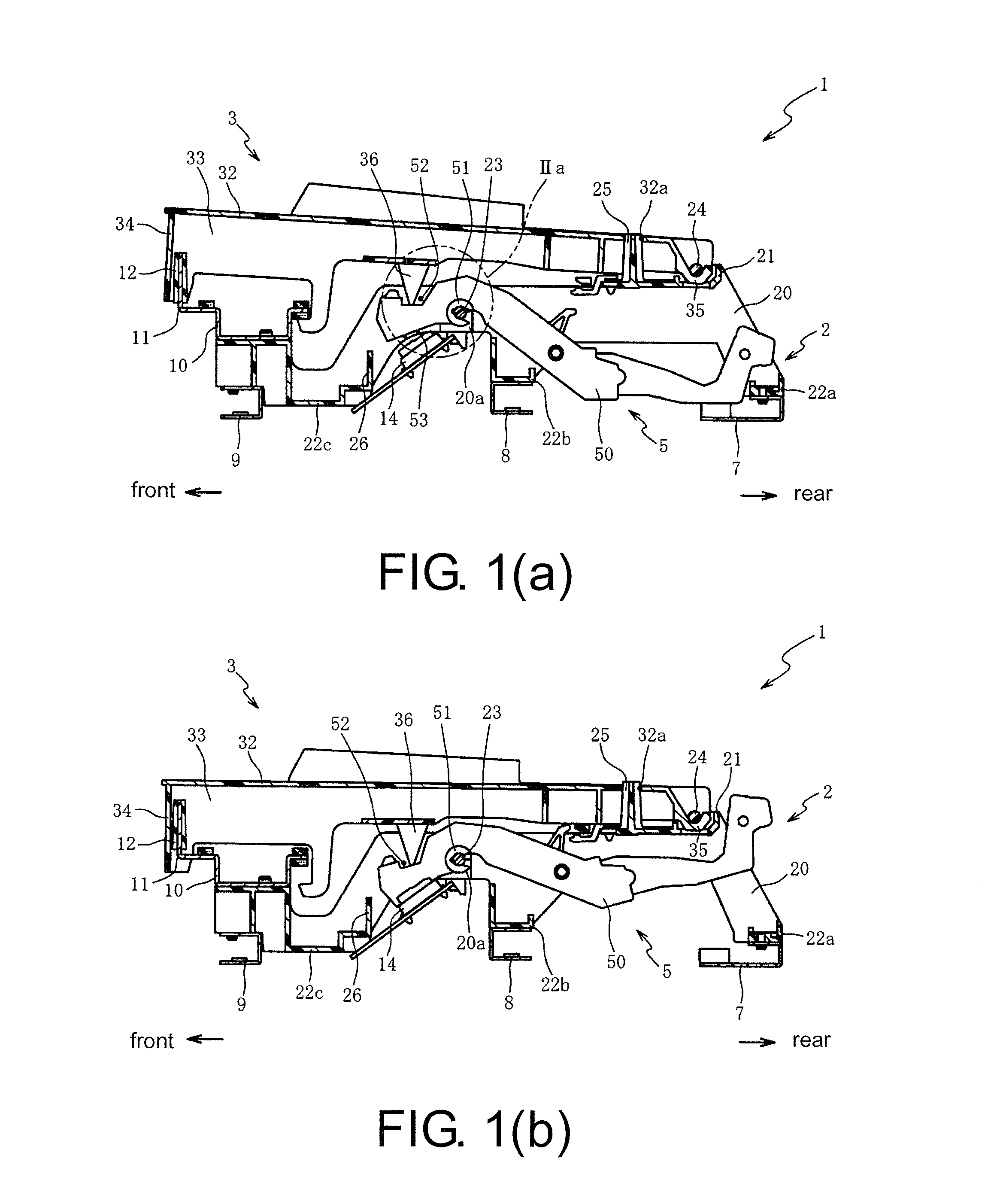
[0043]Hereinafter exemplary embodiments of the invention are described with reference to the affixed figures. FIG. 1(a) is a cross-sectional view of a keyboard device 1 of the first embodiment and particularly shows the case where a hammer 5 is in a retained state. FIG. 1(b) is a cross-sectional view showing the state where the keyboard device 1 shown in FIG. 1(a) is pressed. The case where the hammer 5 is in the retained state refers to a state that a hammer support shaft 23 is retained (pivotally supported) by a bearing 51 of the hammer 5. Moreover, in this embodiment, in the longitudinal direction of a key 3, the side of a key support shaft 24, which is the center of rotation of the key 3, is the rear and the side opposite thereto is the front.

[0044]The keyboard device 1 is a device disposed in an electronic musical instrument to output a signal corresponding to the operation of the key 3. In particular, with the keyboard device 1, the hammer 5 can be correctly installed by a sim...

second embodiment

[0084]The keyboard device 100 of the second embodiment is a device that shifts the hammer 5 in the temporarily secured state to the retained state through the key pressing operation by forming the parts, which are in contact with each other when the hammer 5 is in the temporarily secured state, on a vertical wall 26 (a portion of the chassis bottom wall 22c) and the hammer 5.

[0085]Therefore, the keyboard device 100 differs from the first embodiment in that the vertical wall 26, which is erected upward from the rear of the chassis bottom wall 22c, extends above the vertical wall 26 of the first embodiment. That is, the keyboard device 100 shifts the hammer 5 in the temporarily secured state to the retained state through the key pressing operation by forming a vertical wall side contact part C on the upper rear portion of the vertical wall 26 and bringing the vertical wall side contact part C in contact with the side surface 54 of the hammer 5 (the surface that is inclined obliquely d...


PUM


Abstract

The invention provides a keyboard device of an electronic musical instrument, wherein a hammer can be installed correctly by a simple operation of pressing a key. The keyboard device of the electronic musical instrument includes: a chassis; a key disposed rotatably on the chassis and extending from the rear to a front; a support shaft disposed on the chassis in front of the rotation center; a hammer rotating in conjunction with the key along with pressing on the front of the key; a retaining hole formed through the hammer and retaining the support shaft; a guide groove guiding the support shaft in the retaining hole; and a shifting means, shifting from a temporarily secured state to a retained state, and pressing the hammer in the temporarily secured state toward the rear to shift the hammer to the retained state along with the pressing on the front of the key.

Description

CROSS REFERENCE TO RELATED APPLICATIONS[0001]This application claims the priority benefit of Japan Application No. 2015-071965, filed on Mar. 31, 2015. The entirety of the above-mentioned patent application is hereby incorporated by reference herein and made a part of this specification.BACKGROUND OF THE INVENTION[0002]Field of the Invention[0003]The invention relates to a keyboard device of an electronic musical instrument and more particularly relates to a keyboard device of an electronic musical instrument, in which the hammer can be installed correctly by a simple operation of pressing the key.[0004]Description of Related Art[0005]Conventionally, electronic musical instruments such as an electronic piano are known. In the electronic musical instrument, e.g. the electronic piano, a hammer is provided rotatably under the key. When the key is pressed, the hammer rotates against its own weight and therefore can apply a predetermined load to the key when the key is pressed and create...

Claims


Application Information

Patent Timeline
Patent Type & Authority Patents(United States)
IPC IPC(8): G10C3/12G10H1/34
CPCG10H1/34G10H1/346G10H2220/221
Inventor TAKATA, YUKIHIDEMOROHASHI, YUKIHIROUNO, SHIRO
Owner ROLAND CORP
Why Eureka
Try Eureka