Wireless power transfer and rapid charging system and method with maximum power tracking

a wireless transmission and charging system technology, applied in the direction of electric power, electric vehicles, transportation and packaging, etc., can solve the problems of limited transmission range, poor transmission efficiency, shortcoming in practice, etc., and achieve the effect of reducing output impedance, improving wireless transmission efficiency, and increasing transmission distan

Active Publication Date: 2017-02-28
NATIONAL YUNLIN UNIVERSITY OF SCIENCE AND TECHNOLOGY
View PDF6 Cites 7 Cited by
  • Summary
  • Abstract
  • Description
  • Claims
  • Application Information

AI Technical Summary

Benefits of technology

[0006]Therefore it is a primary object of the present invention to provide a wireless power transfer and rapid charging system with maximum power tracking and a method for the same that perform wireless charging in different environments. The transmission distance is increased, the output impedance is reduced and the wireless transmission efficiency is dramatically improved. At the same time, the speed of wireless charging is increased.

Problems solved by technology

However, the wireless charging system with the expected functions also has shortcoming in practice such as limited transmission range, poor transmission efficiency, limited wireless environment, etc.

Method used


Image

  • Wireless power transfer and rapid charging system and method with maximum power tracking
  • Wireless power transfer and rapid charging system and method with maximum power tracking
  • Wireless power transfer and rapid charging system and method with maximum power tracking

Examples


Embodiment Construction

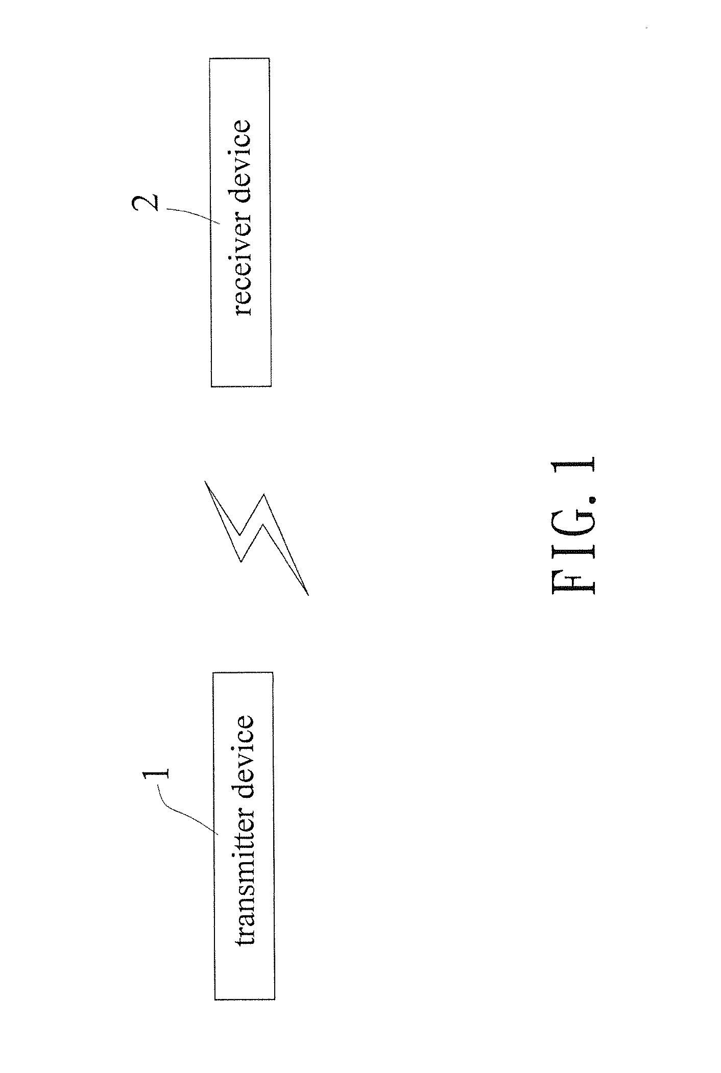
[0032]Refer to FIG. 1, the present invention mainly includes a transmitter device 1 and a receiver device 2.

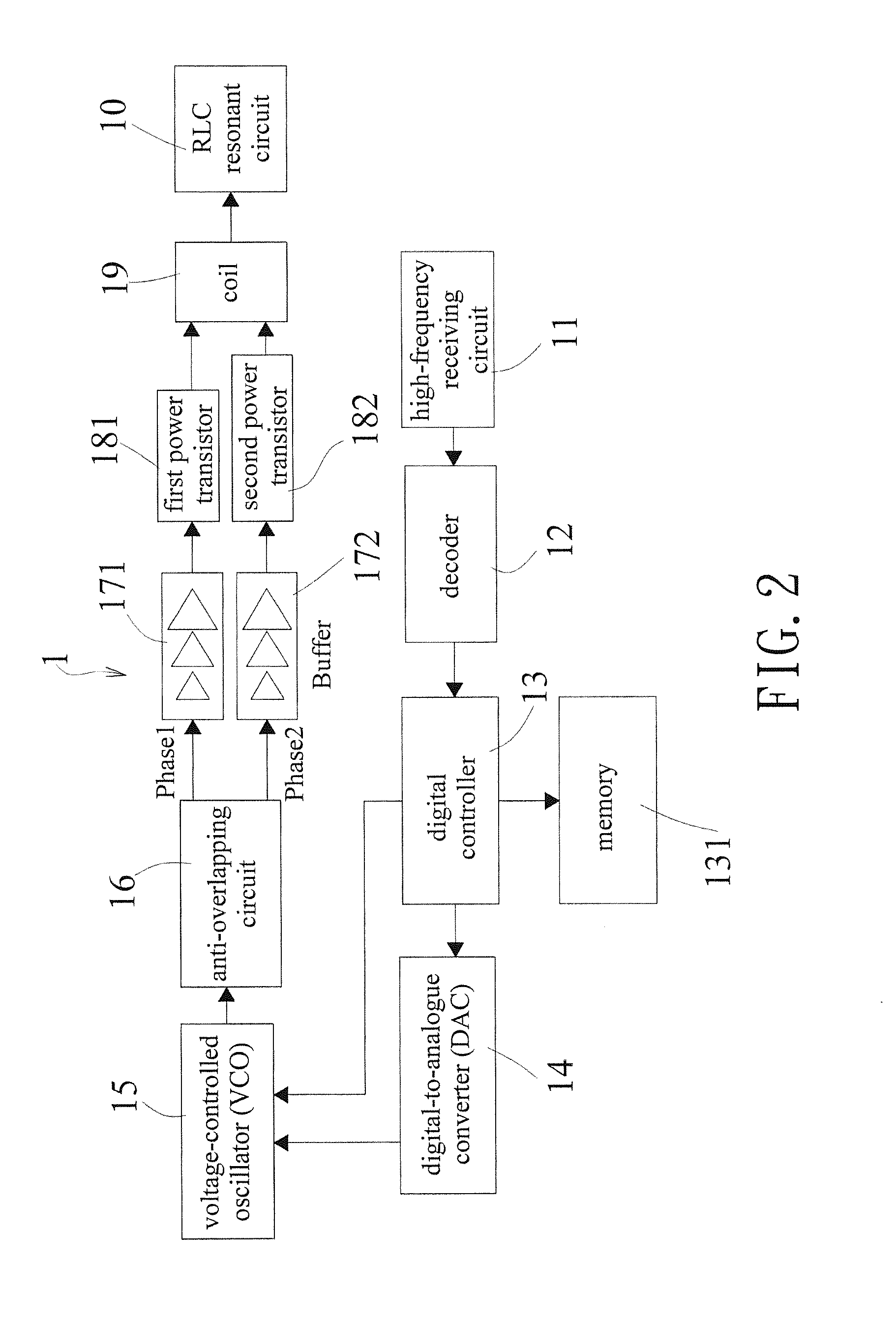
[0033]Refer to FIG. 2, a block diagram showing circuit structure of the transmitter device 1 is revealed. The transmitter device 1 consists of a high-frequency receiving circuit 11, a decoder 12, a digital controller 13, a digital-to-analogue converter (DAC) 14, a voltage-controlled oscillator (VCO) 15, an anti-overlapping circuit 16, a phase-1 buffer circuit 171, a phase-2 buffer circuit 172, a first power transistor 181, a second power transistor 182, a coil 19 and a RLC resonant circuit 10. The high-frequency receiving circuit 11 is for receiving inductive energy of the receiver device 2 and is connected to the decoder 12. The decoder 12 is for decoding the inductive energy of the receiver device 2 and is connected to the digital controller 13. The digital controller 13 is connected to both a memory 131 and the DAC 14. Both the digital controller 13 and the DAC 14 are conne...


PUM


Abstract

A wireless power transfer and rapid charging system with maximum power tracking and a method for the same are revealed. The system includes a transmitter device and a receiver device. First the transmitter device performs maximum power tracking and outputs a fixed resonant frequency. Now the receiver device charges a battery. A voltage detection circuit of the receiver device is detecting charging state of the battery. A high-frequency receiving circuit of the transmitter device checks whether a high-frequency transmission circuit transmits a fully-charged signal. When the high-frequency receiving circuit of the transmitter device receives the fully-charged signal that represents the battery is fully charged, the transmitter device shuts down the power and enters standby mode. Thereby wireless charging can be carried out in different environments. The greater transfer distances, lower output impedance, and higher wireless transmission efficiency can be achieved. The speed of wireless charging is also increased.

Description

BACKGROUND OF THE INVENTIONField of the Invention[0001]The present invention relates to a wireless power transfer and charging system and a method for the same, especially to a wireless power transfer and rapid charging system with maximum power tracking and a method for the same that carry out wireless charging in different environments. An optimal transfer frequency is found, the system provides longer transmission distance, reduced output impedance, greater wireless transmission efficiency, and higher speed of wireless charging.Descriptions of Related Art[0002]Wireless charging is also called inductive charging or non-contact inductive charging. Energy is transferred from a charger to a device by near-field induction (inductive coupling). The device uses the energy received for its own operation and charging of the battery. No physical wire connection is required between the charger and the device. Thus there is no contact metal exposed outside for the charger and the device. Thi...

Claims


Application Information

Patent Timeline
Patent Type & Authority Patents(United States)
IPC IPC(8): H02J7/02H02J5/00H02J7/00
CPCH02J7/025H02J5/005H02J7/007H02J50/12
Inventor HSIA, SHIH-CHANGFAN, JHEN-WUN
Owner NATIONAL YUNLIN UNIVERSITY OF SCIENCE AND TECHNOLOGY
Why Eureka
Try Eureka