Multi-channel ECG measurement

a multi-channel, ecg technology, applied in the field of signal measurement accuracy improvement, can solve the problem of typical noise of measurements

Active Publication Date: 2017-03-14
BIOSENSE WEBSTER (ISRAEL) LTD
View PDF16 Cites 9 Cited by
  • Summary
  • Abstract
  • Description
  • Claims
  • Application Information

AI Technical Summary

Problems solved by technology

Because of this and other environmental factors, in medical procedures such as mapping the electrical activity of the heart, the measurements are typically relatively noisy.

Method used


Image

  • Multi-channel ECG measurement
  • Multi-channel ECG measurement
  • Multi-channel ECG measurement

Examples


Embodiment Construction

Overview

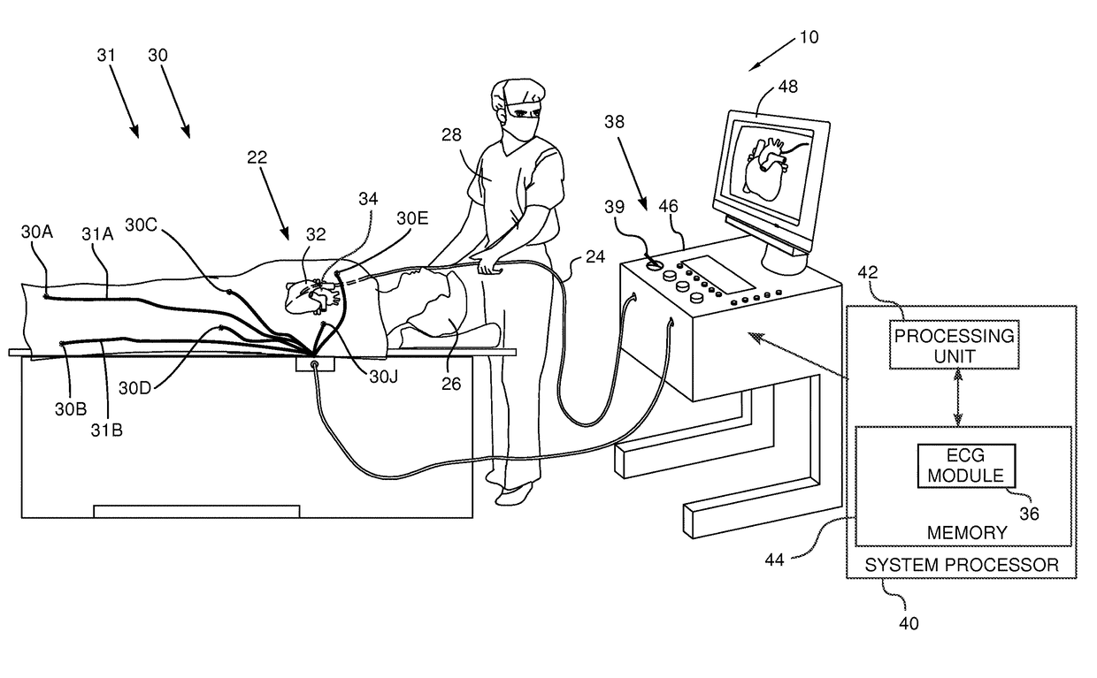
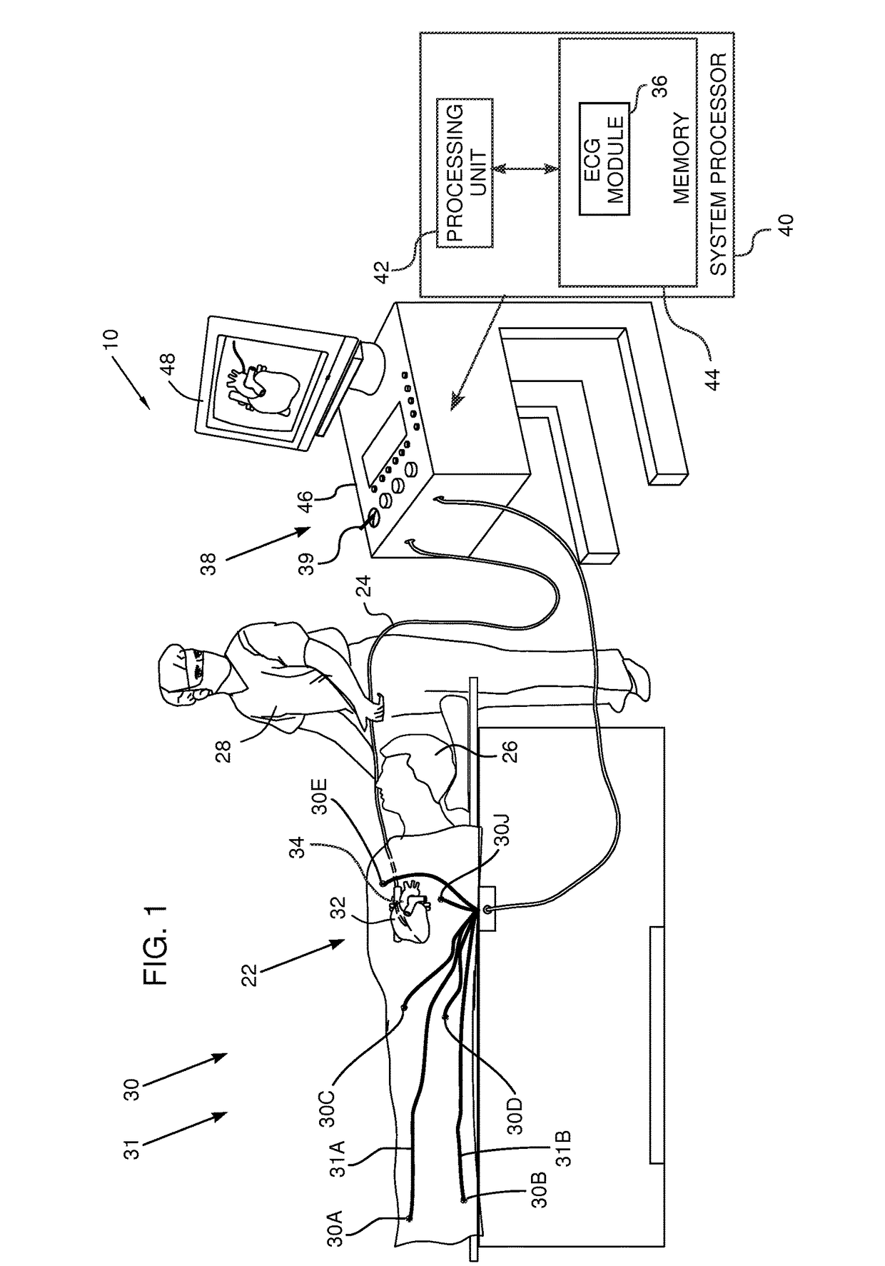
[0026]An embodiment of the present invention provides a system for measuring and compensating channel inaccuracy caused by pick up from sources and channel component variations. The measurement and compensation is typically necessary because the subject may be in an environment where she / he picks up extraneous electrical signals, such as power line signals. The physiological signals may comprise any electrical signals generated by electrical activity of the subject, such as electromyograph (EMG), electroencephalograph (EEG), or electrocardiograph (ECG) signals. For simplicity, the following description assumes the electrical signals are ECG signals.

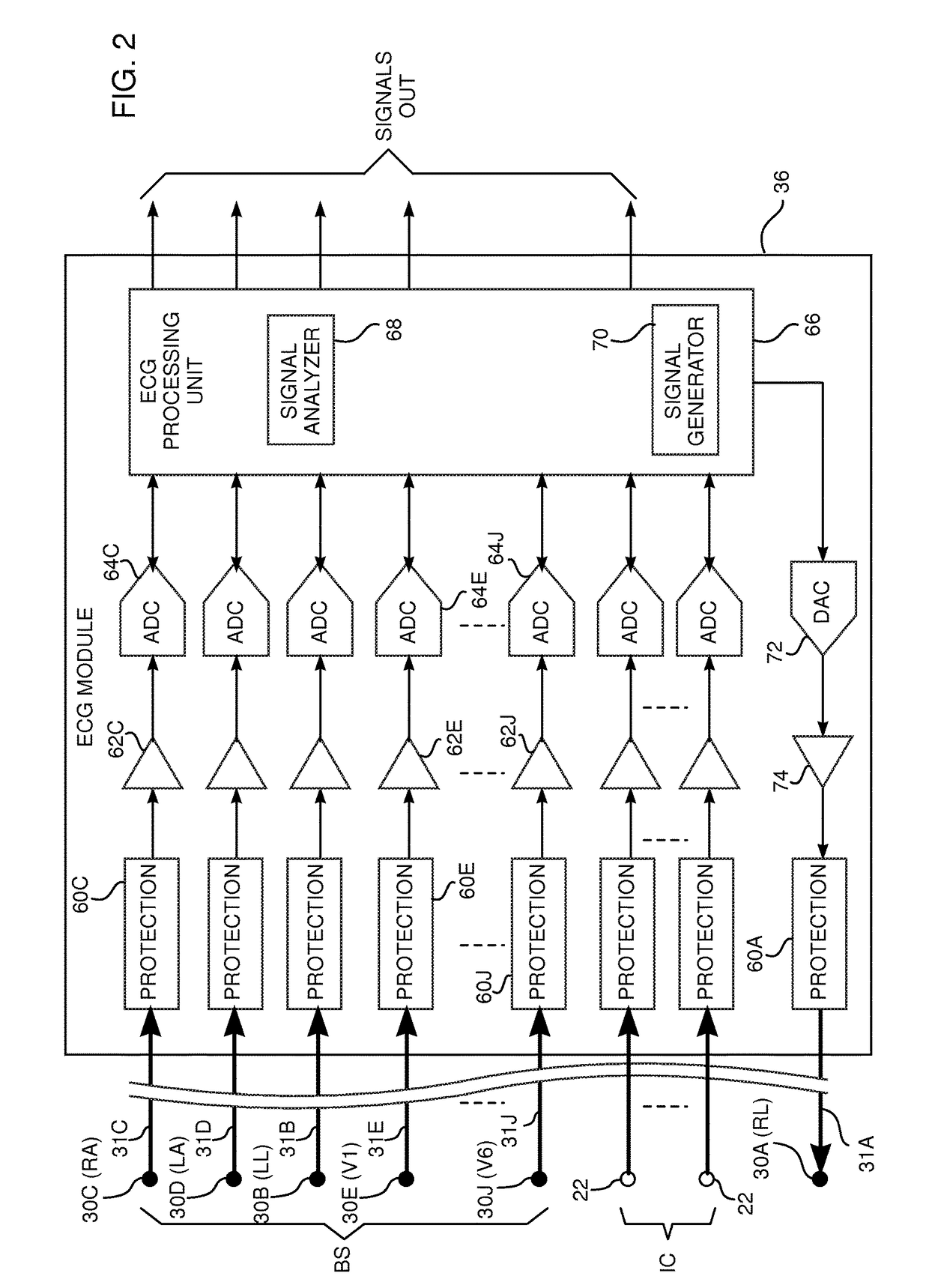
[0027]In order to provide the correction, a known calibration signal is injected into the subject via an injection reference electrode attached to the subject. The calibration signal typically comprises a spectrum of frequencies. Input electrodes are also attached to, or connected to, the subject. The electrodes, in the case of EC...


PUM


Abstract

A method for acquiring electrical signals from a living subject, including injecting, via an injection electrode attached to the subject, a known calibration signal to the subject and measuring respective levels of output signals generated at input electrodes attached to the subject in response to the calibration signal. The method further includes deriving respective weighting factors for the input electrodes in response to the respective levels, and applying the respective weighting factors to physiological signals acquired by the input electrodes, so as to generate respective corrected physiological signals.

Description

FIELD OF THE INVENTION[0001]The present invention relates generally to improvement in the accuracy of signal measurement, and reduction of interference in signal measurement, and specifically to reduction of interference in electrocardiograph (ECG) measurements.BACKGROUND OF THE INVENTION[0002]Electrocardiograph (ECG) signals include signals that are measured from leads external to the heart, typically that are attached to the body surface (BS), as well as those from intra-cardiac (IC) electrodes contacting the heart. The signals are inherently relatively low level signals and have relatively high impedance sources. Because of this and other environmental factors, in medical procedures such as mapping the electrical activity of the heart, the measurements are typically relatively noisy. A system to increase the accuracy of the measurements, and to reduce the effect of the noise on the measurements would be beneficial.SUMMARY OF THE INVENTION[0003]An embodiment of the present inventi...

Claims


Application Information

Patent Timeline
Patent Type & Authority Patents(United States)
IPC IPC(8): A61B5/0408A61B5/0402A61B5/04A61B5/00A61B5/296A61B5/308
CPCA61B5/04085A61B5/04001A61B5/0402A61B5/04012A61B5/04028A61B5/7203A61B5/7228A61B5/327A61B5/24A61B5/316A61B5/318A61B5/282A61B5/283A61B5/291A61B5/296A61B5/303A61B5/6824A61B5/6828A61B5/7217A61B2560/0223A61B2562/0209
Inventor LEVIN, MICHAELBAR-TAL, MEIR
Owner BIOSENSE WEBSTER (ISRAEL) LTD
Why Eureka
Try Eureka