Rear stop device for a bending machine

Active Publication Date: 2017-03-14
TRUMPF MASCHEN AUSTRIA
View PDF18 Cites 0 Cited by
  • Summary
  • Abstract
  • Description
  • Claims
  • Application Information

AI Technical Summary

Benefits of technology

The present invention aims to improve a rear stop device used in a metal sheet processing machine, such as a bending machine. The invention allows the device to be positioned in a variety of ways to optimize its performance and make the best use of available space. This is achieved through the use of a support arm and a rotary slider joint, which allows for the bearing arm to be positioned in a vertical or horizontal position. This results in more flexibility and efficient use of space.

Problems solved by technology

The stop section of said rear stop device, which is designed as a shearing hub, is thus limited to the half of the shearing lifting unit facing the bending press, as the stop finger cannot adopt a position in which it can be positioned on the side of the shearing lifting unit facing away from the bending press.
A disadvantage of the known embodiments which are controlled by means of linear drives is that there is a relatively high center of gravity of the whole rear stop device.
DE 697 22 935 T2 solves this kinematic disadvantage by the said shearing lift, but has the disadvantage however that the shearing lift needs a lot of space and is limited in its stopping options.
Therefore, it is not possible to achieve a space-saving installation in a metal sheet processing system, if the stop fingers need to have a traversing area that is as large as possible.
Because of the limited positionability of the stop finger in stop direction there are only limited options for processing differently shaped metal sheets, or a very large amount of space is required.
A further disadvantage is that the stop fingers can only be aligned in a horizontal direction.
In this way the application is limited to flat metal sheets that are not prebent.
The significant disadvantage of this is that the rear stop device is not adjusted to the required, free positionability in space which is necessary in modern processing machines.

Method used


Image

  • Rear stop device for a bending machine
  • Rear stop device for a bending machine
  • Rear stop device for a bending machine

Examples


Embodiment Construction

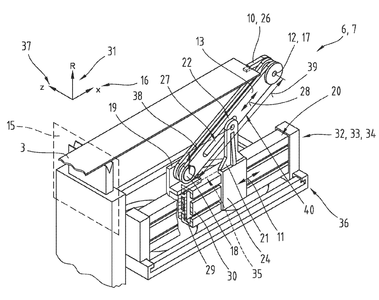
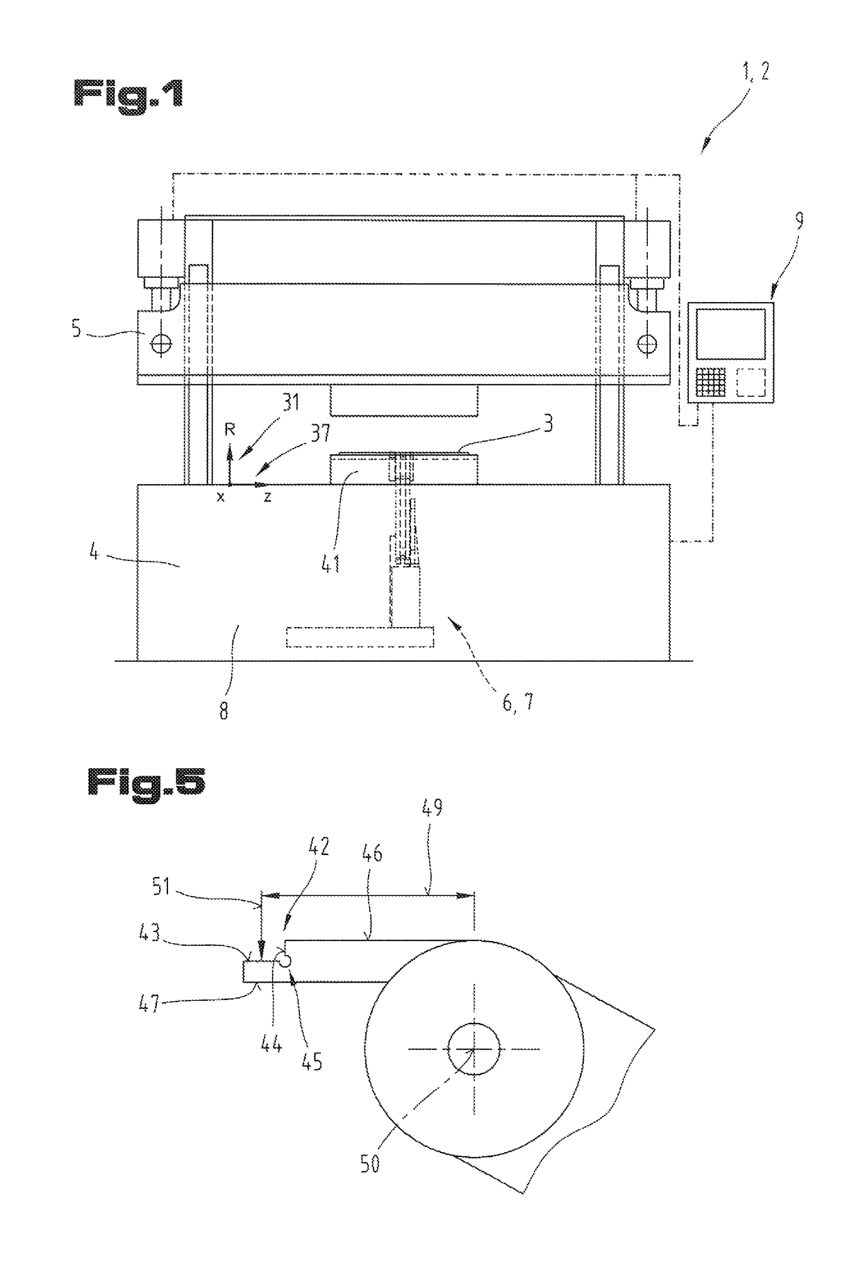
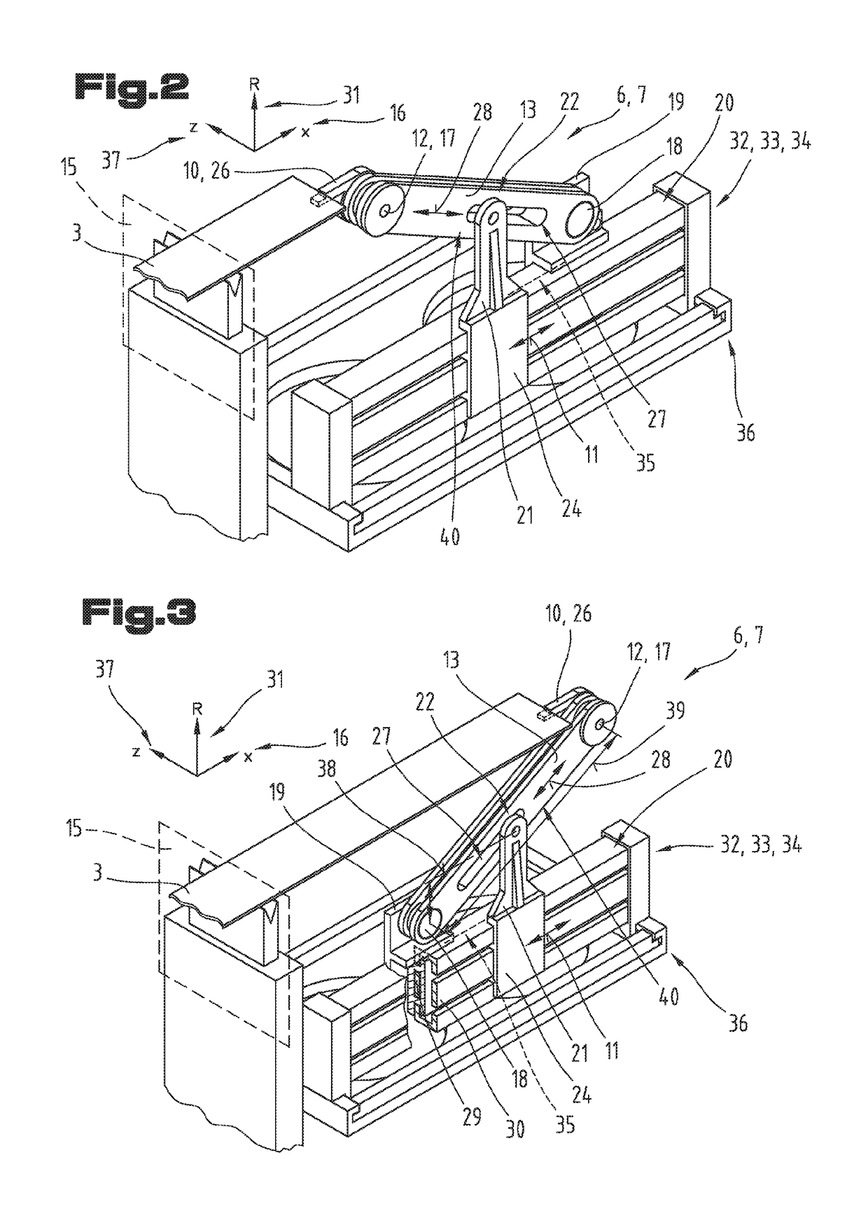
[0035]First of all, it should be noted that in the variously described exemplary embodiments the same parts have been given the same reference numerals and the same component names, whereby the disclosures contained throughout the entire description can be applied to the same parts with the same reference numerals and same component names. Also details relating to position used in the description, such as e.g. top, bottom, side etc. relate to the currently described and represented figure and in case of a change in position should be adjusted to the new position. Furthermore, also individual features or combinations of features from the various exemplary embodiments shown and described can represent in themselves independent or inventive solutions.

[0036]All of the details relating to value ranges in the present description are defined such that the latter include any and all part ranges, e.g. a range of 1 to 10 means that all part ranges, starting from the lower limit of 1 to the up...


PUM

PropertyMeasurementUnit
Fractionaaaaaaaaaa
Fractionaaaaaaaaaa
Lengthaaaaaaaaaa

Abstract

The invention relates to a rear stop unit (7) with a stop and / or gripping and / or measuring element (10) for positioning a sheet (3) to be machined on a bending press. The stop and / or gripping and / or measuring element (10) is arranged on an adjustable bearing arm (13) by means of a pivot joint (12). The bearing arm (13) is connected to a guide rail (20) by means of an additional pivot joint (18) via a guide element (19). The rear stop unit (7) further comprises a support arm (21) which is connected to the bearing arm (13) via a joint (22) and to an additional guide element (24) via a rigid connection, and the support arm is connected to the guide rail (20) via the additional guide element. Furthermore, the joint (22) is designed as a rotational / prismatic joint. The position of the bearing arm (13) can thereby be adjusted by moving the support arm (21) in a linear manner along a guide direction (11) specified by the guide rail (20).

Description

CROSS REFERENCE TO RELATED APPLICATION[0001]This application is the National Stage of PCT / AT2014 / 050136 filed on Jun. 18, 2014, which claims priority under 35 U.S.C. §119 of Austrian Application No. A 50404 / 2013 filed on Jun. 20, 2013, the disclosures of which are incorporated by reference. The international application under PCT article 21(2) was not published in English.BACKGROUND OF THE INVENTION[0002]1. Field of the Invention[0003]The invention relates to a rear stop device comprising a stop and / or gripping and / or measuring element.[0004]2. The Prior Art[0005]Generic rear stop devices, in particular with linear guides, are known from the prior art in a plurality of embodiments.[0006]DE 697 22 935 T2 discloses a rear stop device, which is structured on the basis of a shearing lifting unit. Here two horizontally aligned stop fingers are arranged on a common guide rail running in a direction parallel to the sheet metal bending line, and can be displaced individually in this directi...

Claims


Application Information

Patent Timeline
IPC IPC(8): B21D43/26B21D5/02B21D5/00
CPCB21D43/26B21D5/002B21D5/02B21D43/026
Inventor ANGERER, GERHARDFREUDENTHALER, KLEMENSGAGGL, JOSEFHOERL, MATTHIASTHEIS, HELMUTWEISS, THOMASWALDHERR, MANFRED
Owner TRUMPF MASCHEN AUSTRIA
Why Eureka
Try Eureka