
Header assembly

a header and assembly technology, applied in the direction of coupling devices, two-part coupling devices, electrical devices, etc., can solve the problems of insufficient coupling between the interface housing and the shell in some known connector systems to meet standard-defined retention requirements, and the cost of many different molds or dies

Active Publication Date: 2017-03-14
TE CONNECTIVITY CORP
View PDF20 Cites 73 Cited by
  • Summary
  • Abstract
  • Description
  • Claims
  • Application Information

AI Technical Summary

Benefits of technology

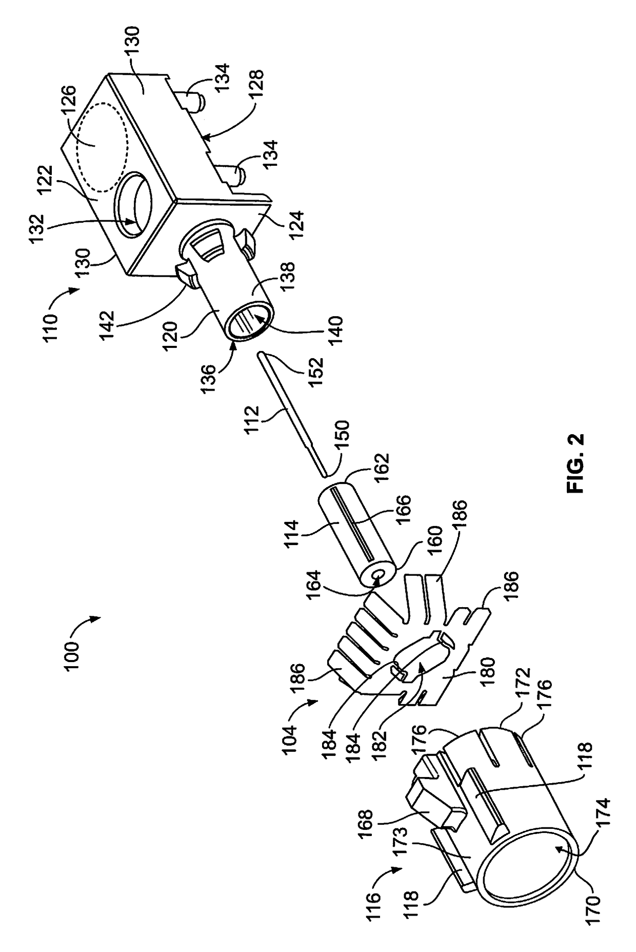
The invention relates to a header assembly for a connector, which comprises a center contact, a dielectric body, an outer housing, and a nose cone. The center contact is surrounded by the dielectric body, which in turn is held by the outer housing. The outer housing has a rear shell and an outer contact extending forward from the rear shell. The outer contact receives the center contact and the dielectric body. The outer contact has multiple locking tabs extending from an exterior thereof, which engage with multiple latches on the nose cone to secure it to the outer housing in different rotational orientations. The technical effects of the invention include improved electrical connection, durability, and reliability of the header assembly.

Problems solved by technology

Manufacturing many different molds or dies is expensive.
Additionally, requiring customers to carry a different part for each desired keying configuration causes additional expense to the customer in terms of inventory and warehousing of inventory.
In addition to being expensive and difficult to require multiple different parts for each desired keying configuration, the coupling between the interface housing and the shell in some known connector systems is inadequate to meet standard-defined retention requirements.
Thus, pulling on a mating connector coupled to the male housing causes the latch to fail below the retention requirement threshold, resulting in the interface housing uncoupling from the shell.

Method used


Image

  • Header assembly
  • Header assembly
  • Header assembly

Examples


Embodiment Construction

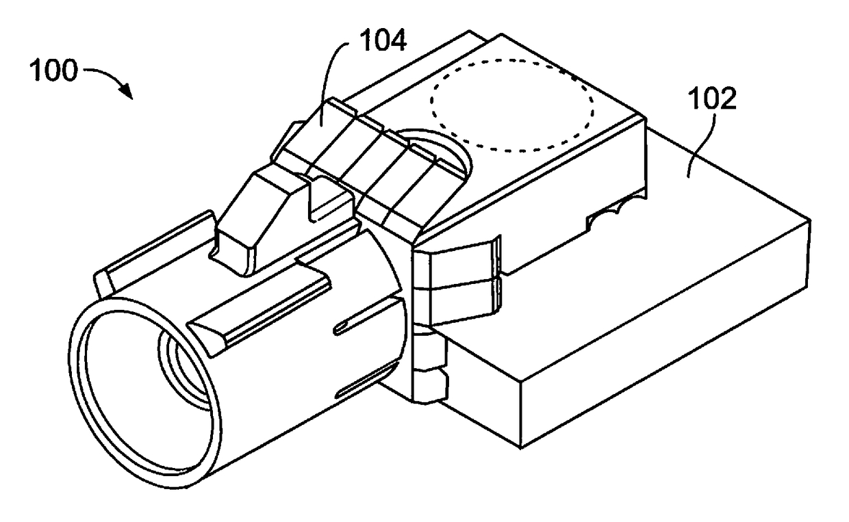
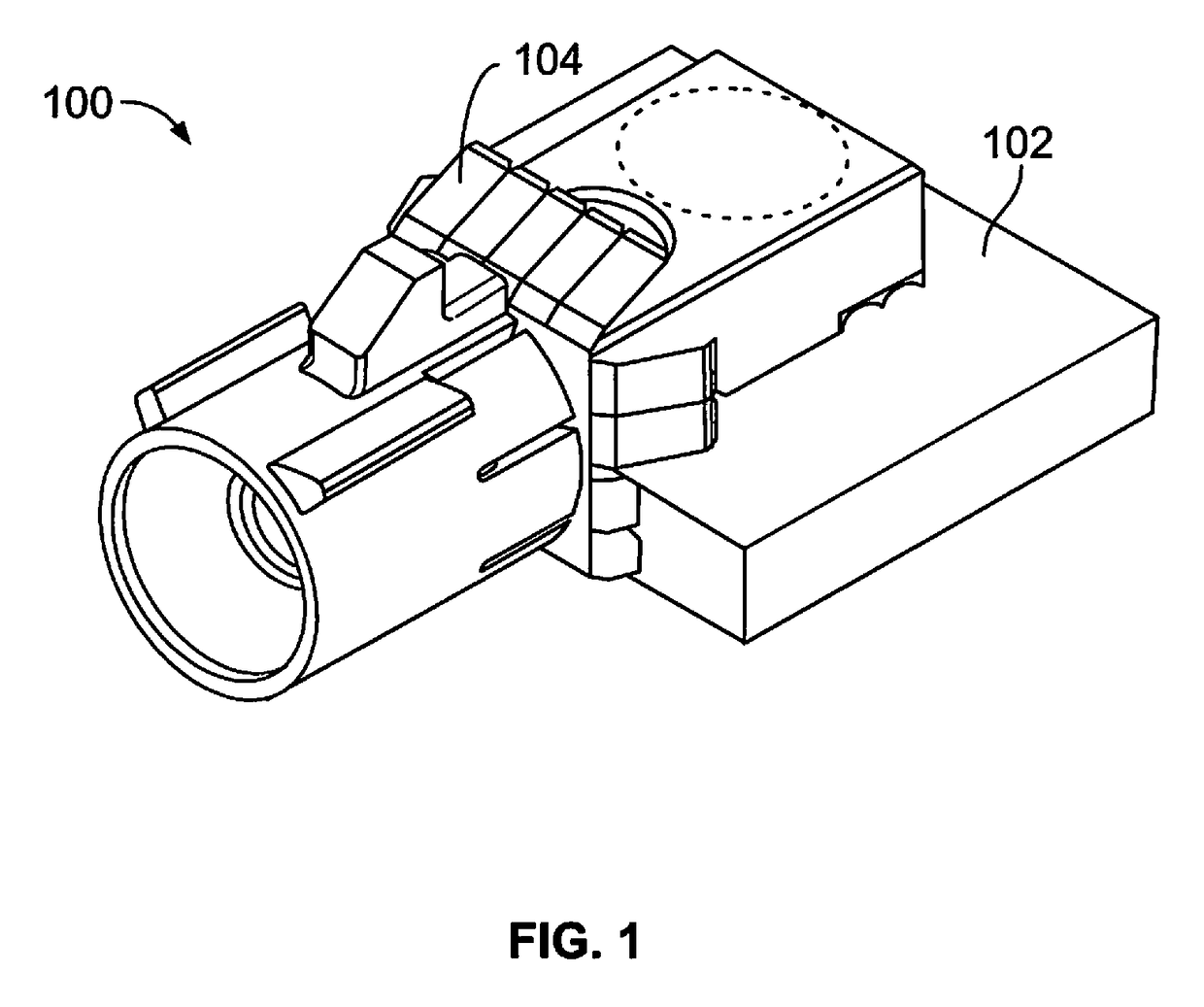
[0019]FIG. 1 is a front perspective view of a header assembly 100 formed in accordance with an exemplary embodiment. The header assembly 100 may be mounted in a device, such as a radio, having a casing that houses components of a communication system. The header assembly 100 may pass through an opening in the casing of the device for mating with a corresponding connector assembly (not shown).

[0020]The header assembly 100 is mounted to a circuit board 102, which may form part of a communication system, such as for an automotive vehicle. For example, the communication system may be used in an automotive application, such as a global positioning system (GPS), car radio, mobile phone, rear-view camera, air bag system, multimedia device system, and the like. The system may have use in other types of applications such as aeronautic applications, marine applications, military applications, industrial applications and the like. The circuit board 102 may form part of an antenna. The circuit ...


PUM


Abstract

A header assembly includes an outer housing holding a center contact and a dielectric body. The outer housing has a rear shell and an outer contact extending forward from the rear shell. The outer contact has a catch extending therefrom positioned forward of the rear shell. The header assembly includes a nose cone coupled to the outer contact. The nose cone surrounds the outer contact. The nose cone has one or more keying ribs along an exterior thereof. The nose cone has a latch engaging the catch to secure the nose cone to the outer housing in one of at least two distinct rotational orientations.

Description

CROSS-REFERENCE TO RELATED APPLICATIONS[0001]This application claims priority to U.S. Provisional Application No. 62 / 089,612, filed 9 Dec. 2014, which is incorporated by reference in its entirety.BACKGROUND OF THE INVENTION[0002]The subject matter herein relates generally to header assemblies.[0003]Radio frequency (RF) coaxial connector assemblies have been used for numerous automotive applications, such as global positioning systems (GPS), car radios, mobile phones, air bag systems, and multimedia devices. Some coaxial connector assemblies are cable assemblies that are terminated to ends of coaxial cables. Coaxial cables typically consist of an outer conductor, an inner conductor, a dielectric, and a jacket or outer insulation. The outer conductor and the inner conductor of the cable electrically interface with corresponding inner and outer contacts of the connector, which may be a male or a female connector. Other coaxial connector assemblies are terminated to a circuit board rath...

Claims


Application Information

Patent Timeline
Patent Type & Authority Patents(United States)
IPC IPC(8): H01R12/00H01R13/645H01R24/50H01R13/506H01R24/38H01R13/627H01R13/6583H01R24/52H01R103/00
CPCH01R24/38H01R13/506H01R13/6456H01R24/50H01R13/6272H01R13/6583H01R24/52H01R2103/00H01R2201/26
Inventor LANE, DAVID JAMESBAKER, JESSE ALAN
Owner TE CONNECTIVITY CORP
Learn More