Flush mounted spider assembly

a technology of rotary table and insert, which is applied in the direction of drilling rods, drilling casings, drilling pipes, etc., can solve the problems of not being able to adapt to different pipe sizes or rotary table openings, and not being able to distinguish spiders from elevators, etc., to achieve quick and easy adaption, reduce manufacturing and inventory, and be easily removed

Active Publication Date: 2017-03-21
M&C
View PDF12 Cites 0 Cited by
  • Summary
  • Abstract
  • Description
  • Claims
  • Application Information

AI Technical Summary

Benefits of technology

[0008]A spider can be made from several individual segments, that when configured together will fit in the non-circular recess drive of a rotary table. The spider will fit loosely into the rotary table so that any loads can be transferred directly to the rotary table recess. A mounting structure will serve to hold the non-continuous parts of the spider together until it is placed in the rotary table. The non-continuous peripherally distributed parts of the assembly have a slip manipulation surface which slopes downward toward the vertical center line of the rotary table. On each surface a slip will travel, so that when the slip moves down, it also radially constricts. With upward motion the slip radially expands. The slips also have a changeable set of dies to allow quick and easy adaption to different size pipes. The slips are powered by a linear motor in both directions. This will allow for powered radial movement in both directions. The slips will be timed together so that they contact and evenly apply pressure on the pipe being gripped. At least one section of the spider and timing ring may also be easily removed so that a pipe can pass through at least one of its sides. By making some of these parts identical, manufacturing and inventory can be reduced.

Problems solved by technology

In some cases, there is no way to distinguish a spider from an elevator.
When composite spiders are prepared by the manufacturer for use in the field, they have limited adaptability to function for a variety of pipe sizes and, if considerable diversity of use is planned, several spiders have to be on hand or readily available.
They are purpose built to a specific size and not readily adaptable to different pipe sizes or rotary table openings.

Method used


Image

  • Flush mounted spider assembly
  • Flush mounted spider assembly
  • Flush mounted spider assembly

Examples


Embodiment Construction

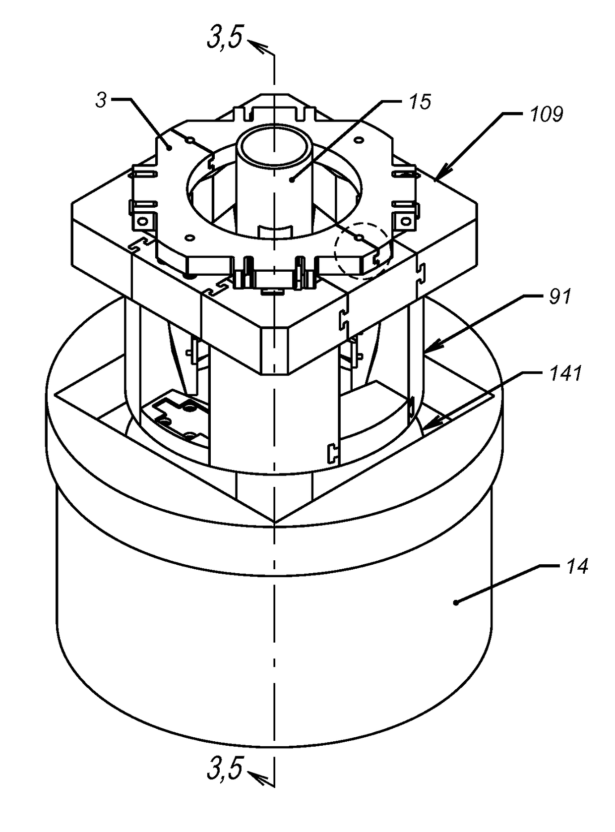
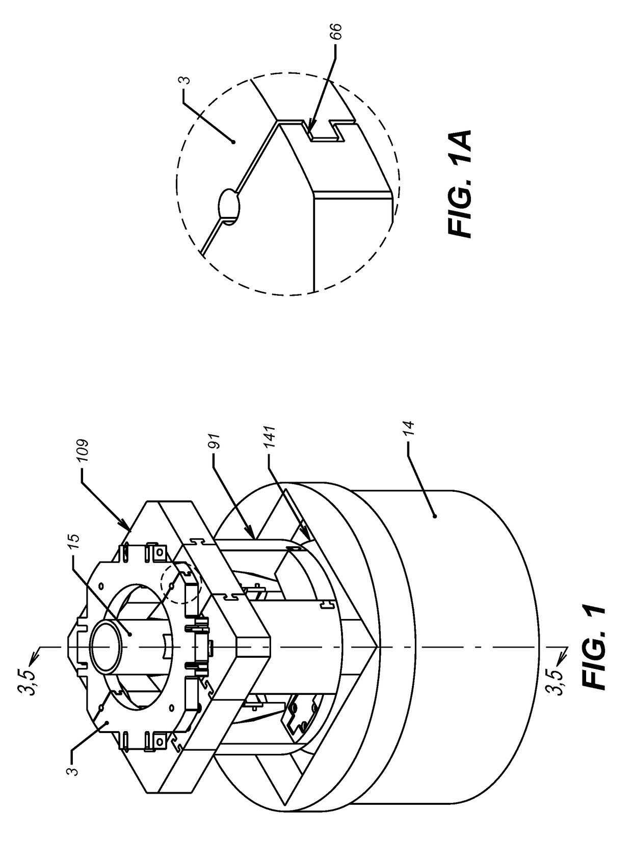
[0014]In FIG. 1 the complete assembly 109 fits the recess in the rotary table 14. The pipe 15 is placed through the center of the assembly 109 and rotary table 14. When lowered, outer surface 91 is radially restrained by surface 141 of rotary table 14. The detailed view shows the tongue and groove design 66 used to keep the timing plate 3 in time, but allows easy separation, if disassembly is required. Other means of removable communication can be used.

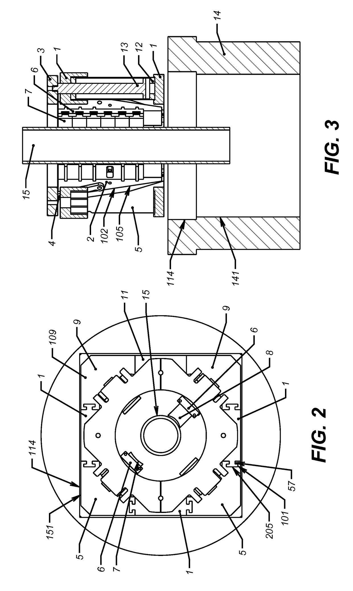
[0015]In FIG. 2 the non-circular recess 114 fits the non-circular geometry 151 made by the assembly 109 that will transmit torque.

[0016]The assembly 109 is made up from slip carriers 5 and 9 and intervening mounting structures 1 and 11. The slip carriers 5 and 9 and mounting structure 1 and 11 are held together by a T-Slot 57, where slot surface 205 and 101 restrict each other. These t-slots can be formed in different orientations. Other methods of removable joining can be used such as bolts or pins. The pipe 15 is fixed by the dies 8...


PUM


Abstract

A rotary table has a non-circular drive recess in the central opening which carries an assembly of mounting structures and slip carriers that when joined together fit in the non-circular drive recess. The plurality of slip carriers are distributed about the periphery of the drive recess are extended down into the central opening of the rotary table. A slip and die arrangement is situated on each slip carrier. Slip manipulation drive cylinders, are distributed about the assembly periphery and move a synchronizer plate that moves the slips vertically to grip or release pipe extending through the opening of the rotary table.

Description

FIELD OF THE INVENTION[0001]The field of the invention is a slip carrier insert for a rotary table of a drilling rig and more particular where the slip carriers are integrated into a frame to fit a non-circular shaped opening in the rotary table.BACKGROUND OF THE INVENTION[0002]Drill strings are usually supported by spiders that fit in the opening of the rotary table. They usually have a slip bowl in which slips are peripherally distributed to surround the pipe to be gripped. The slip bowl opens upwardly. When a pipe string suspended in the well is to be gripped by the spider, the slips are moved downward. The slip bowl surface urges the downwardly moving slips to move radially inward to bear upon, and grip, the pipe. When the slips grips the pipe and load is transferred, the resulting downward force adds to the radially inward thrust of the slips, and largely defines the essential elements of what has become known as a failsafe system. Teeth carried by the slips contact the pipe to...

Claims


Application Information

Patent Timeline
Patent Type & Authority Patents(United States)
IPC IPC(8): E21B19/10E21B19/07
CPCE21B19/10E21B19/07
Inventor MULLINS, ALBERT AUGUSTUSHICKL, MATTHEW J.
Owner M&C
Why Eureka
Try Eureka