Connector device

a technology of connecting parts and connectors, applied in the direction of coupling device connections, electrical equipment, connections, etc., can solve the problems of increasing the insertion load, easy wear and tear of the contact parts of the male terminal and the female terminal, etc., to reduce the insertion load, reduce the wear and tear of the contact parts, and reduce the friction resistance

Active Publication Date: 2017-03-21
YAZAKI CORP
View PDF17 Cites 6 Cited by
  • Summary
  • Abstract
  • Description
  • Claims
  • Application Information

AI Technical Summary

Benefits of technology

[0006]Illustrative aspects of the present invention provide connector device having a female terminal that can reduce a friction resistance at the time of inserting a male terminal, thereby reducing an insertion load and also reducing wear of contact portions.

Problems solved by technology

Therefore, there is a problem that the spring load causes a friction resistance and increases the insertion load.
Because the insertion involves receiving of the friction resistance, there is also a problem that contact portions of the male terminal and the female terminal are easily worn away.

Method used


Image

  • Connector device
  • Connector device
  • Connector device

Examples


Embodiment Construction

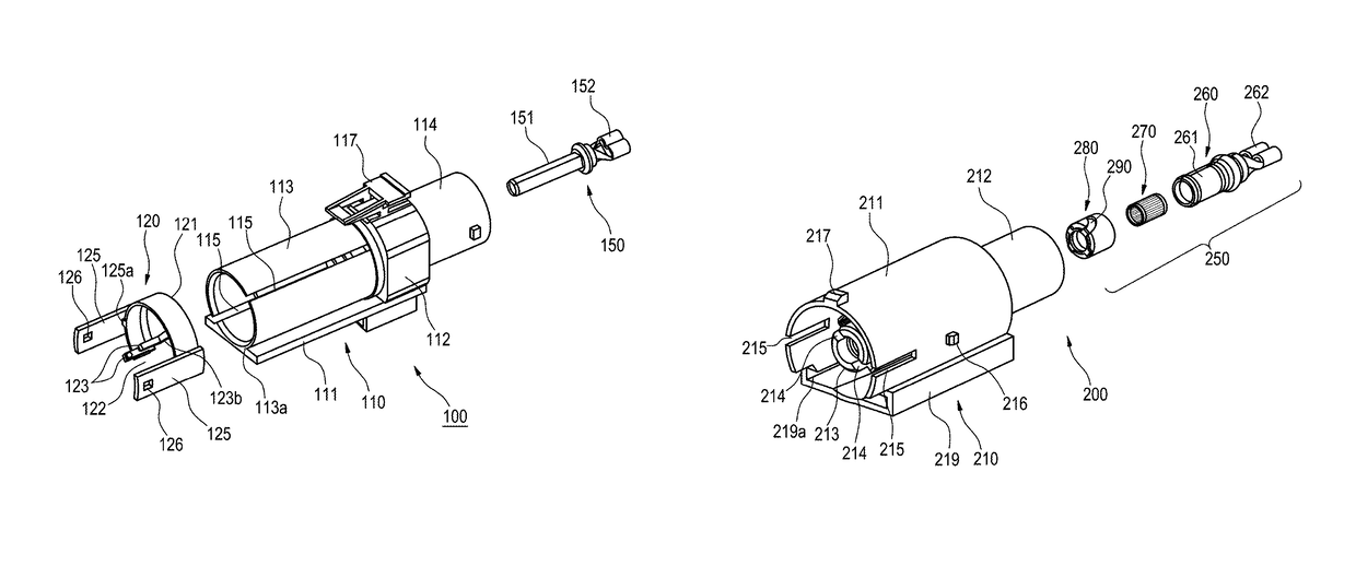
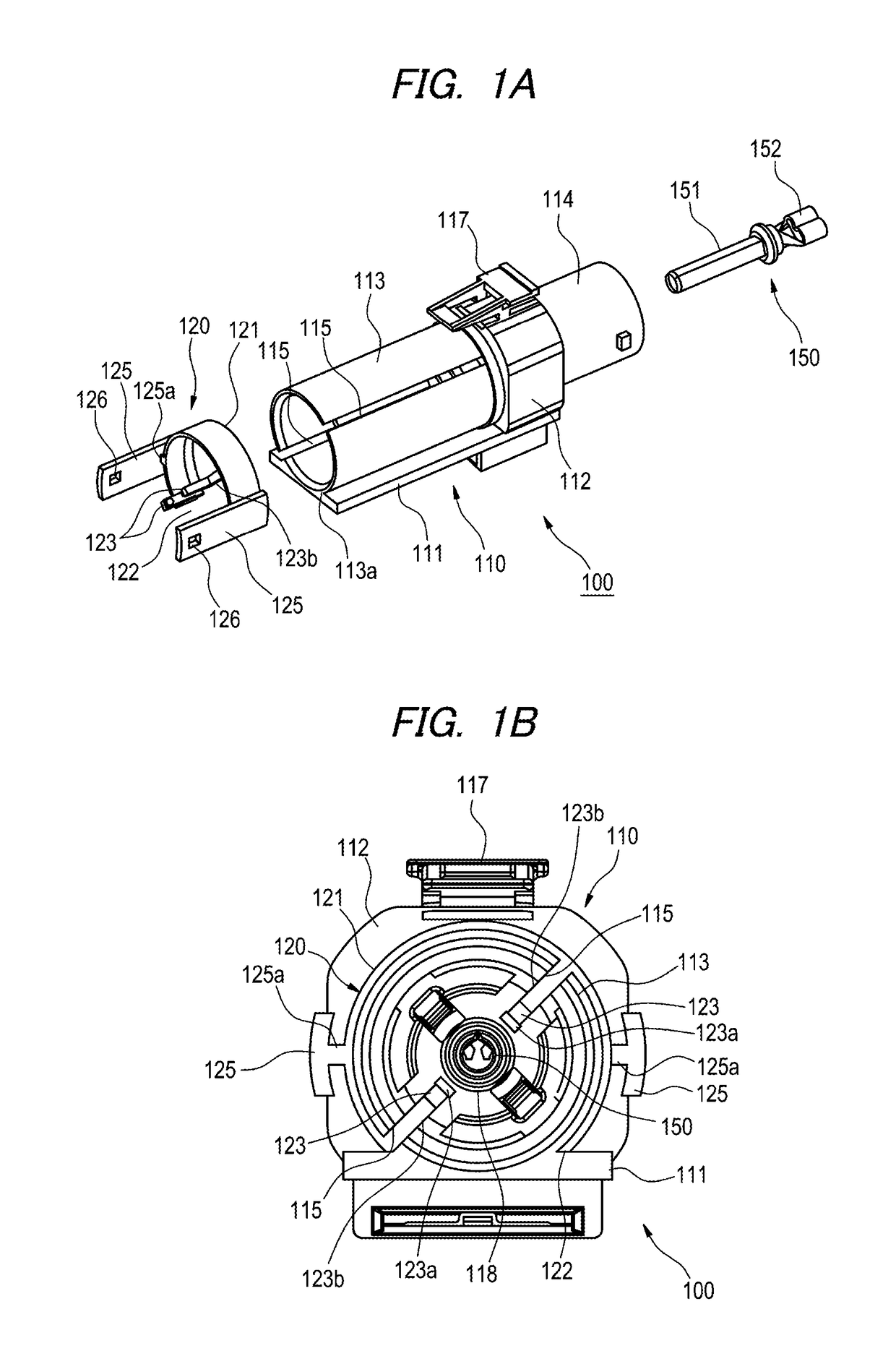
[0035]Hereinafter, embodiments of the present invention will be described with reference to the drawings. A connector device according to an embodiment of the present invention includes a first connector 100 as shown in FIGS. 1A and 1B, and a second connector 200 as shown in FIGS. 2A and 2B. As shown in FIG. 1A, the first connector 100 includes a first connector housing 110, a slider 120 mounted to this first connector housing 110 so as to slide in an axial direction, and a pin-shaped male terminal 150 held inside the first connector housing 110.

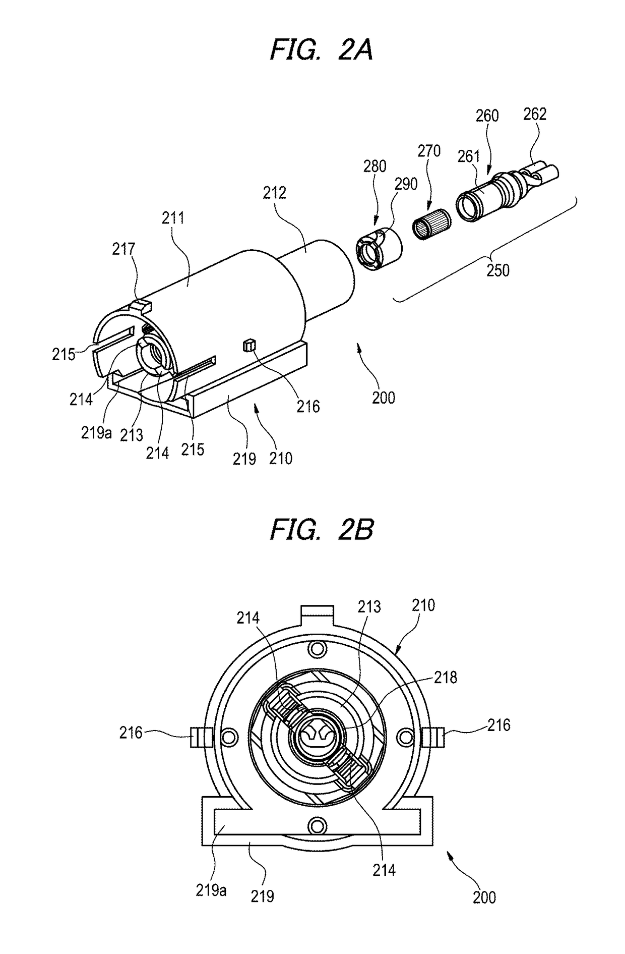
[0036]As shown in FIG. 2A, the second connector 200 includes a second connector housing 210 adapted to be engaged with the first connector housing 110 of the first connector 100, and a female terminal 250 held inside this second connector housing 210. When the first connector 100 and the second connector 200 are accurately engaged with each other, and further, the slider 120 is slid from an initial position to an operation position, the fema...


PUM


Abstract

A contact member provided inside a cylindrical contact holder of a female terminal has a diameter variable portion including a number of metal string members whose both ends are held by front side and rear side holding rings. When a slider is moved in a connector engaged state, a linear movement of a cam projection provided on the slider is converted into a rotational movement of a rotary ring by a cam groove 290, so that the front side holding ring fixed to the rotary ring is rotated to apply a twist to the diameter variable portion, whereby the metal string members are deformed into a hyperboloidal shape and the smallest inner diameter portion thereof is brought into pressure contact with a male terminal.

Description

CROSS REFERENCE TO RELATED APPLICATIONS[0001]This application is a continuation of International Patent Application No. PCT / JP2014 / 075214 filed on Sep. 24, 2014, claiming priority from Japanese Patent Application No. 2013-197126 filed on Sep. 24, 2013, the contents of which are incorporated herein by reference.FIELD OF INVENTION[0002]The present invention relates to a connector device.BACKGROUND ART[0003]JP 4209775 B2 describes an example of a female terminal having a radially resilient contact member. As shown in FIGS. 12 and 13, this female terminal 10 has a cylindrical sleeve 20, and a cylindrical contact member 30 inserted inside the cylindrical sleeve 20. A plurality of engaging parts 21 are arranged at an interval in a circumferential direction, at both axial ends of the cylindrical sleeve 20. The cylindrical contact member 30 has a plurality of axially extending contact strips (thin strips for contacts) 31, and also has a plurality of engaging parts 32 arranged at an interval...

Claims


Application Information

Patent Timeline
Patent Type & Authority Patents(United States)
IPC IPC(8): H01R13/187H01R13/193H01R13/629H01R4/48H01R4/50
CPCH01R4/5008H01R4/4881H01R13/193H01R13/62911H01R13/187
Inventor ANDO, SHUHEI
Owner YAZAKI CORP
Why Eureka
Try Eureka