Clip for attachment of floor carpet

An installation and carpet technology, applied in the direction of the device for tightening the carpet, the special position of the vehicle, the vehicle parts, etc., can solve the problems of the female part and the pad cap falling off, the pulling force of the floor pad, and the insertion force of the large shaft. , to reduce the insertion load, avoid misassembly, and achieve the effect of high pull-out force

Active Publication Date: 2021-09-24
NIFCO INC
View PDF8 Cites 0 Cited by
  • Summary
  • Abstract
  • Description
  • Claims
  • Application Information

AI Technical Summary

Problems solved by technology

However, in this operation, the pulling force of the floor mat may be large, or the engagement between the circumferential groove of the female part and the engaging protrusion of the male part-side engaging piece may be released due to a difference in the pulling direction, and the female part may be disengaged. Comes off with cushion cap
In addition, in the operation of inserting the shaft part on the male part side into the cylindrical part on the female part side to engage the engaging convex part with the circumferential groove, it is difficult to displace the shaft part and the elastic engaging piece in the diameter-reducing direction. Large shaft insertion force, lack of operability

Method used


Image

  • Clip for attachment of floor carpet
  • Clip for attachment of floor carpet
  • Clip for attachment of floor carpet

Examples


Embodiment Construction

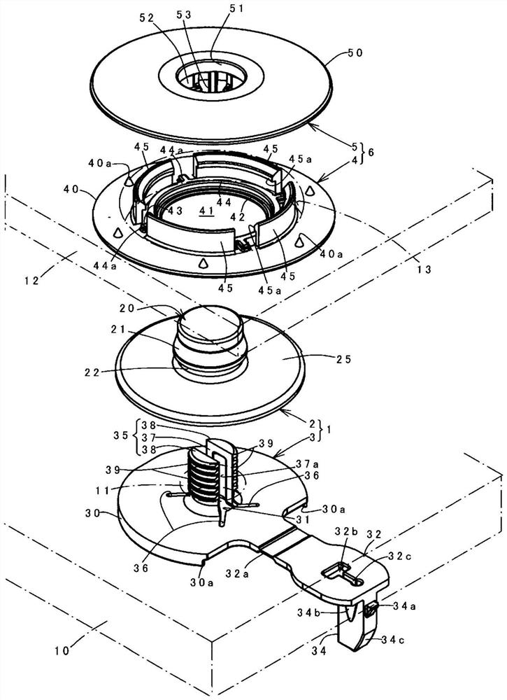
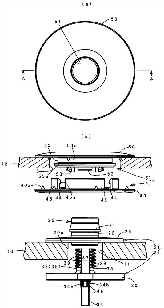
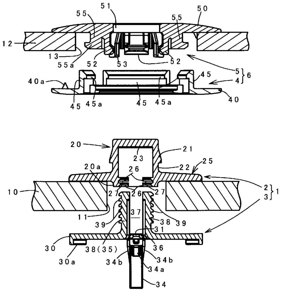
[0035] Hereinafter, the best mode of the present invention will be described with reference to the drawings. In this description, according to the structure of the clip for installing the floor carpet of the vehicle and its operating characteristics, the structure of the clamping body for installing the floor mat and its operating characteristics, and the relationship between the clip and the clamping body, that is, for relative The connection structure of the clip and the clamping body of the floor carpet mounting floor mat, and the order of the modification will be described in detail.

[0036] (The structure of the clip)

[0037] The clip 1 for attaching a floor carpet according to the embodiment includes: a female member 2 having a cylindrical portion 20 , an upper flange portion 25 protruding from the outer periphery of the cylindrical portion 20 , and an engaging member provided on the inner periphery of the cylindrical portion 20 . parts 26, 27; the male member 3 has a...


PUM


Abstract

The present invention provides a clip for attachment of a floor carpet, which is composed of a female member and a male member, and which is capable of imparting a high pull-out force. The clip (1) for attachment of a floor carpet is provided with: a male member (3) having a lower flange portion (30) and a shaft portion (35); the female member (2) has an upper flange portion (25) protruding from the outer periphery of a cylindrical portion (20). The cylindrical portion (20) is engaged with the protruding portion of the through shaft portion by penetrating the shaft portion through an insertion hole of the floor carpet (10), so that the floor carpet is attached in a state where the floor carpet is clamped by the upper and lower flange portions, and a floor mat or the like placed on the upper surface of the floor carpet can be fixed by the cylindrical portion of the female member. The male member has a hole portion (37) that passes through the lower flange portion and the shaft portion in the axial direction, and an engagement protrusion portion (39) that protrudes on the outer periphery of the shaft portion. The male member has a restricting member (34). In a state in which the engagement protrusion portion is elastically engaged with an engagement portion (26, 27) provided on the inner periphery of the cylindrical portion with respect to the female member, the restriction member is pressed into the hole portion so that the engagement of the engagement protrusion portion from the engagement portion cannot be released.

Description

technical field [0001] The present invention relates to a clip for installing a floor carpet of a vehicle, which is mounted on a floor carpet of an automobile or the like, and which fixes articles such as a floor mat placed on the floor carpet. Background technique [0002] Figure 11 It is a clip structure disclosed in Patent Document 1, and (a) shows a female part (cap part) 5 and a male part (pin part) 4 constituting a clip for installing a floor carpet, and a floor mat 1 that can be fixed to the female part 5 . The relationship between the cushion cap 6, (b) shows the use state that the cushion cap 6 is fixed to the female part 5. Among them, the male member 4 has: a lower flange portion 4a disposed on the lower surface of the floor carpet 3; a bottomed cylindrical shaft portion 4b protruding from the upper surface of the lower flange portion and penetratingly provided in the insertion hole 3a of the floor carpet. a pair of elastic engaging pieces 7 and 7 divided by a s...

Claims


Application Information

Patent Timeline
IPC IPC(8): F16B5/06F16B21/08B60N3/04
CPCF16B5/0628F16B5/0692F16B21/082B60N3/046A47G27/0418A47G27/04B60N3/044
Inventor 古内英浜本拓哉
Owner NIFCO INC
Why Eureka
Try Eureka