waterproof plug

A waterproof plug and lip technology, which is applied in the field of waterproof plugs, can solve the problems of inability to stably ensure the waterproof performance of the replacement part, insufficient waterproof performance, etc., and achieve the effects of preventing cracks, ensuring waterproof performance, and reducing insertion load.

Inactive Publication Date: 2018-03-20
YAZAKI CORP
View PDF7 Cites 0 Cited by
  • Summary
  • Abstract
  • Description
  • Claims
  • Application Information

AI Technical Summary

Problems solved by technology

However, the inventors of the present application considered that when the waterproof plug 1 is assembled to the electric wire 8, when an external force is applied to the electric wire 8 and the electric wire 8 swings, at this time, if the number of replacement parts is one, then with the swing of the electric wire 8 Shaking occurs, and as a result, the waterproof performance at the replacement part cannot be stably ensured
That is, the inventors of the present application thought that simply adopting the technique of Patent Document 2 is not sufficient and that there is room for improvement.

Method used


Image

  • waterproof plug
  • waterproof plug
  • waterproof plug

Examples


Embodiment 1

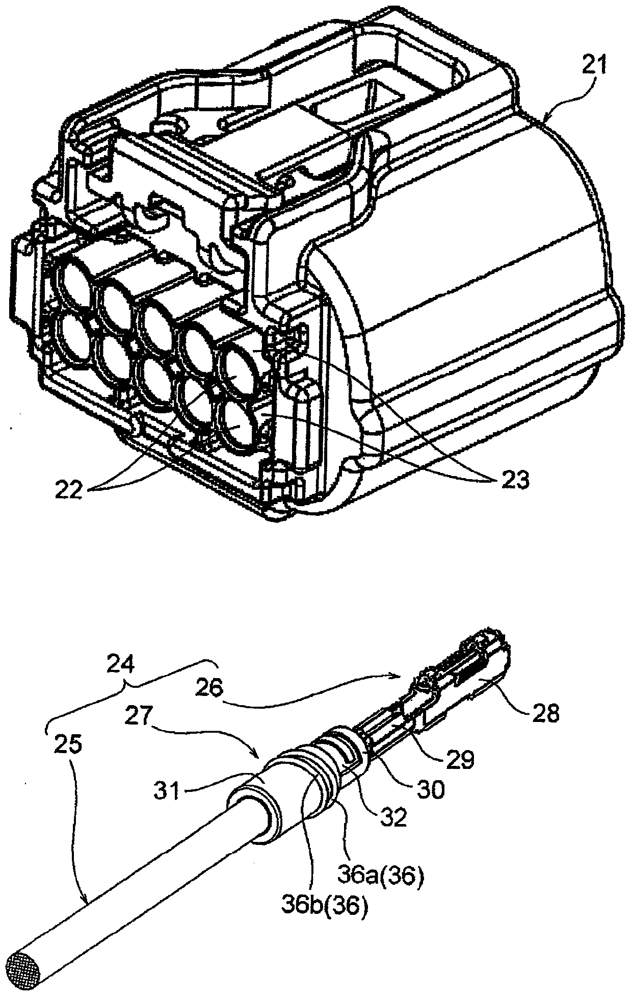
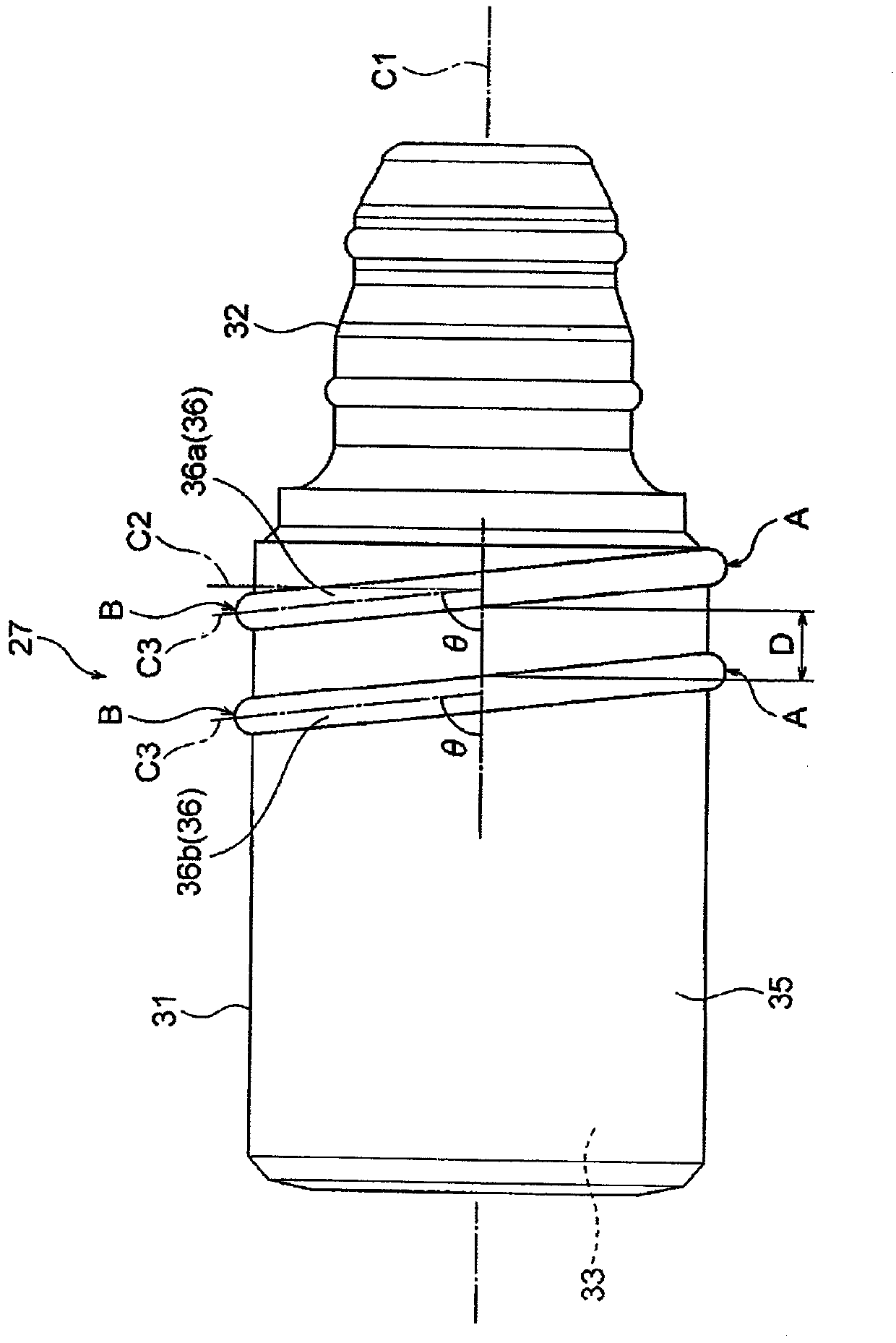
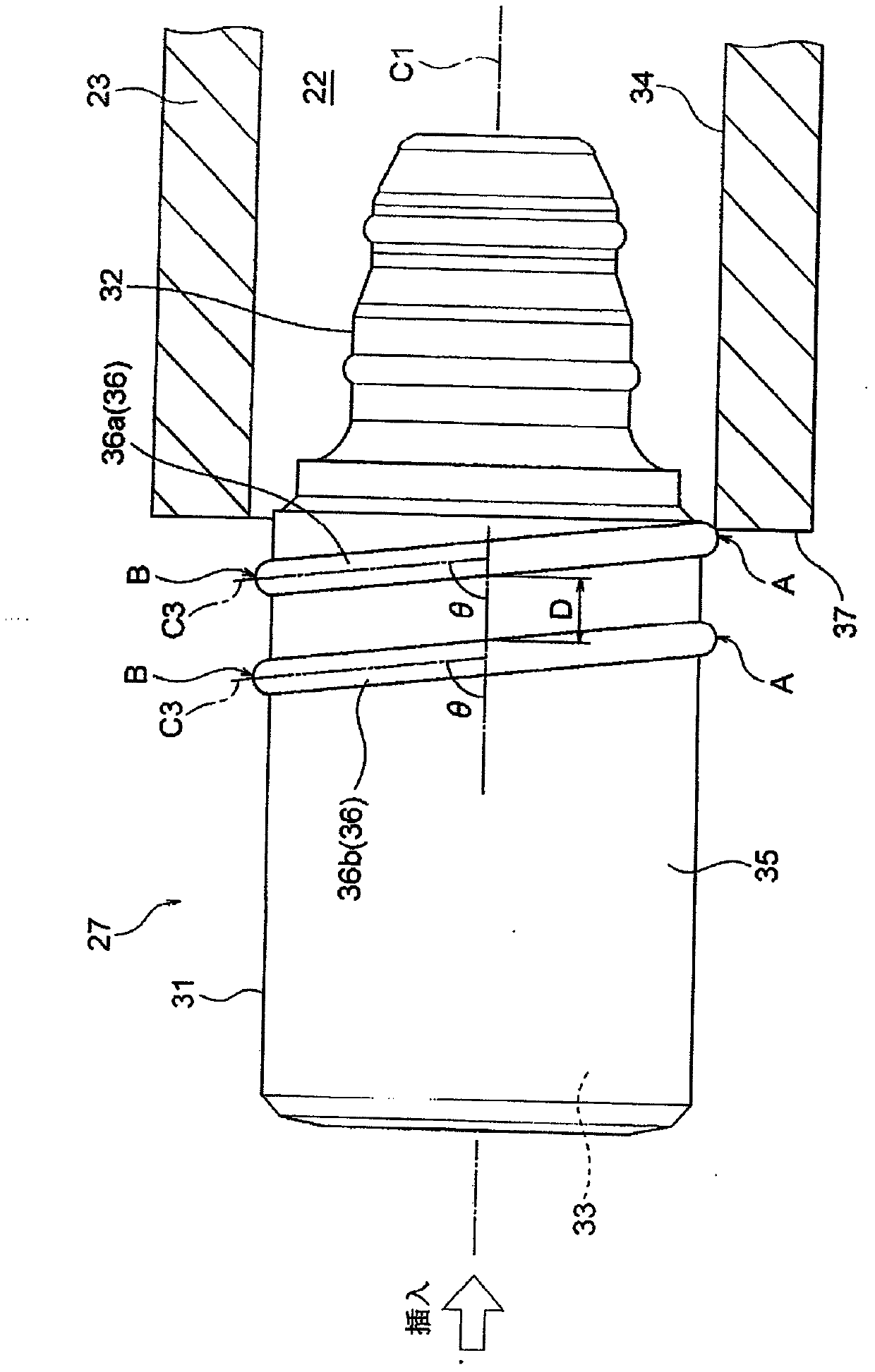
[0074] Hereinafter, Embodiment 1 will be described with reference to the drawings. figure 1 It is a perspective view showing an electric wire with a terminal to which the waterproof plug of the present invention is mounted, and a connector case serving as a storage destination for the electric wire with a terminal. in addition, figure 2 is the side view of the waterproof plug, image 3 is a schematic diagram showing the state when the waterproof plug is inserted into the terminal housing chamber, Figure 4 It is a front view of the waterproof plug schematically showing the first contact portion when the waterproof plug is inserted into the terminal accommodating chamber.

[0075]

[0076] exist figure 1 In , reference numeral 21 shows a connector housing of a connector used for electrical connection. The connector housing 21 is a molded product obtained by injection-molding an insulating resin material, and has a plurality of terminal accommodating chambers 22 . The ...

Embodiment 2

[0093] Hereinafter, Embodiment 2 will be described with reference to the drawings. Figure 5 It is a perspective view showing a terminal-provided electric wire equipped with a waterproof plug according to another example of the present invention, and a connector case serving as a storage destination of the terminal-provided electric wire. in addition, Image 6 is the side view of the waterproof plug, Figure 7 is a schematic diagram showing the state when the waterproof plug is inserted into the terminal housing chamber, Figure 8 It is a front view of the waterproof plug schematically showing the first contact portion when the waterproof plug is inserted into the terminal accommodating chamber. In addition, the same code|symbol is attached|subjected to the component which is basically the same as the said Example 1, and detailed description is abbreviate|omitted.

[0094]

[0095] exist Figure 5 Among them, the connector housing 21 has a plurality of terminal accommoda...


PUM


Abstract

The present invention provides a waterproof plug. The waterproof plug (27) is a substantially cylindrical elastic member, the inner side of which is liquid-tightly attached to the sheathed outer peripheral surface of the electric wire, and the outer side is liquid-tightly attached to the connector housing. The inner peripheral surface (34) of the terminal accommodation chamber (22) of the body. An annular lip is formed on the outer peripheral surface of the waterproof plug (27). The lip is formed in plural. The plurality of lips are formed as inclined lips (36) extending in an oblique direction with respect to the axis of the hole through which the electric wire is inserted. The plurality of inclined lips (36) are arranged side by side at predetermined intervals (D) along the axis. The plurality of inclined lips (36) respectively have an initial contact portion (A) and a final contact portion (B) with the inner peripheral surface (34) of the terminal accommodation chamber (22).

Description

technical field [0001] The present invention relates to a waterproof plug that is liquid-tightly adhered to the outer surface of a sheath of an electric wire and the inner peripheral surface of a terminal accommodating chamber of a connector housing. Background technique [0002] A connector is provided at the end of a wire harness composed of a plurality of electric wires. In order to make the connector waterproof, a waterproof plug has been used in the past (specifically, a waterproof plug is used to ensure the waterproof performance between the connector housing and the electric wires). bolt). [0003] exist Figure 9 and Figure 10 In (a), for example, a waterproof plug 1 (so-called rubber stopper) disclosed in Patent Document 1 below is formed in a substantially cylindrical shape having elasticity. The waterproof plug 1 has an electric wire insertion hole 2 formed therein. In addition, lip portions 4 and 5 are formed on the outer peripheral surface 3 of the waterproo...

Claims


Application Information

Patent Timeline
Patent Type & Authority Patents(China)
IPC IPC(8): H01R13/52
Inventor 新味義史坂元信幸
Owner YAZAKI CORP
Why Eureka
Try Eureka