Coil insertion method and coil insertion device

A coil insertion and coil technology, which is applied in the direction of electromechanical devices, manufacturing motor generators, electrical components, etc., can solve the problem of enlarged coil end size, achieve the effect of reducing insertion load and preventing damage

Active Publication Date: 2020-01-31
SUMITOMO HEAVY IND LTD
View PDF5 Cites 0 Cited by
  • Summary
  • Abstract
  • Description
  • Claims
  • Application Information

AI Technical Summary

Problems solved by technology

[0005] On the other hand, in the conventional coil insertion method, only concentric windings can be formed for each magnetic pole, so in a motor using such a stator core, the coils partially overlap, and the size of the coil ends becomes large.

Method used


Image

  • Coil insertion method and coil insertion device
  • Coil insertion method and coil insertion device
  • Coil insertion method and coil insertion device

Examples


Embodiment 1

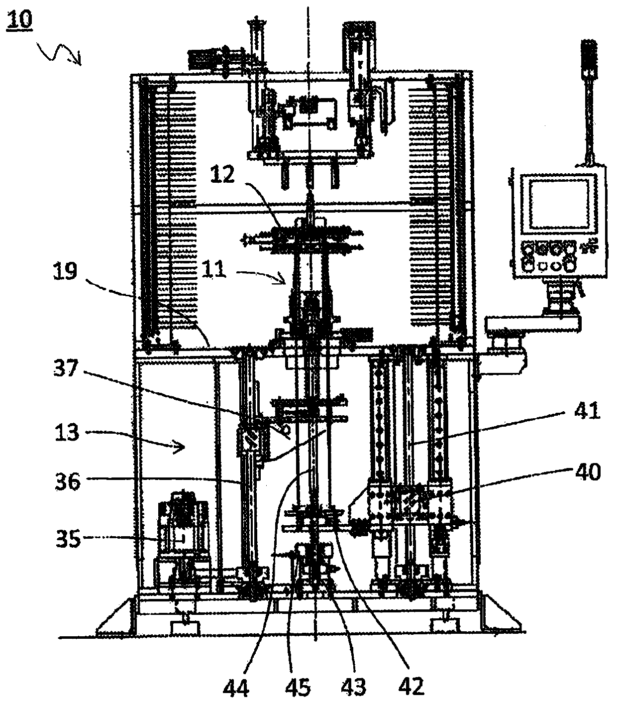
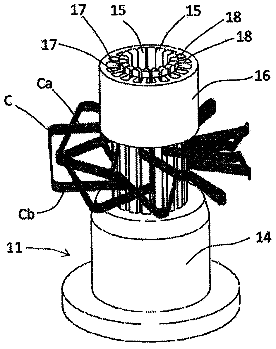
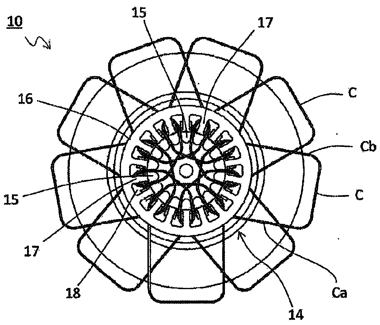
[0087] use Figure 1 to Figure 9 The illustrated coil insertion device of the present invention inserts the coils arranged in a helical shape overlapping each other on the coil insertion jig into the stator core. And, the insertion load at this time was measured, and the result was expressed as Figure 11 Curve C. In addition, in Comparative Example 1, Comparative Example 2, and Example 1, the specifications of the stator core and the coil are the same.

[0088] Such as Figure 11 As shown in the curve A of , when a conventional coil insertion device is used to insert a coil wound concentrically, the insertion load increases slowly and then decreases slowly. However, the peak value of the insertion load becomes very high.

[0089] Depend on Figure 11 It can be seen from the curve B in the figure that when using a conventional coil insertion device to insert coils stacked on top of each other in a helical shape, the insertion load increases significantly in the second hal...


PUM


Abstract

Provided are a coil insertion method and a coil insertion device with which the coil insertion load can be lowered. When coils C are inserted into corresponding slots of a stator core 16 via prescribed gaps between multiple blades 15 possessed by a coil insertion tool and arranged in a ring shape corresponding to the inner teeth 17 of the stator core, the coils are lifted to the vicinity of the upper end of the blades by a lifter 20, which is arranged on the inside of the blades, does not have fins that enter into the gaps between the blades, and has coil retraction grooves in the inner diameter direction. Next, strippers 25, 30 having fins that enter into the gaps between the blades are raised, thereby inserting the coils into the corresponding slots of the stator core.

Description

technical field [0001] The invention relates to a coil insertion method and a coil insertion device for inserting a coil into a slot of a stator core by using a coil insertion jig. Background technique [0002] As a method of attaching the coil to the stator core, a direct winding method in which the coil is directly wound on the inner teeth of the stator core is adopted, and the wound coil is first held in a coil insertion jig and the coil is inserted into the stator core by a coil insertion device. The coil insertion method in the slot. Among them, the coil insertion method has high productivity and can also be applied to parallel windings, so the coil insertion method is widely used. [0003] In the coil insertion method, a coil insertion jig having a plurality of blades arranged in an annular shape corresponding to the internal teeth of the stator core is used, the coil is held in a predetermined gap between the blades of the coil insertion jig, and the blades The top ...

Claims


Application Information

Patent Timeline
Patent Type & Authority Patents(China)
IPC IPC(8): H02K15/085
CPCH02K15/085
Inventor 深渡刚守谷幸次山本泰三
Owner SUMITOMO HEAVY IND LTD
Why Eureka
Try Eureka