Chisel Holder

a chisel and holder technology, applied in the field of chisel holders, can solve the problems of insufficient discharge of working forces, short service life, and breakage of insertion projections, and achieve the effect of reducing stress on insertion projections

Active Publication Date: 2016-03-17
WIRTGEN GMBH
View PDF4 Cites 0 Cited by
  • Summary
  • Abstract
  • Description
  • Claims
  • Application Information

AI Technical Summary

Benefits of technology

[0026]A bit holder according to the present invention can also be characterized in that the lines normal to the first and/or second stripping surfaces extend in inclined fashion with respect to the advance direction, so that transverse forces can reliably be transferred.
[0027]A particularly preferred configuration of the invention is such that a plane receiving the angle bisector is arranged between the first and/or the second stripping surfaces, and that the insertion projection is arranged symmetrically with respect to that plane. As a result of this symmetrical configuration, the bi

Problems solved by technology

The configuration of a bit holder shown in U.S. Pat. No. 3,992,061 cannot discharge the working forces with a sufficiently good service life, especially at high advance speeds.
In particular, the stripping s

Method used


Image

  • Chisel Holder
  • Chisel Holder
  • Chisel Holder

Examples


Embodiment Construction

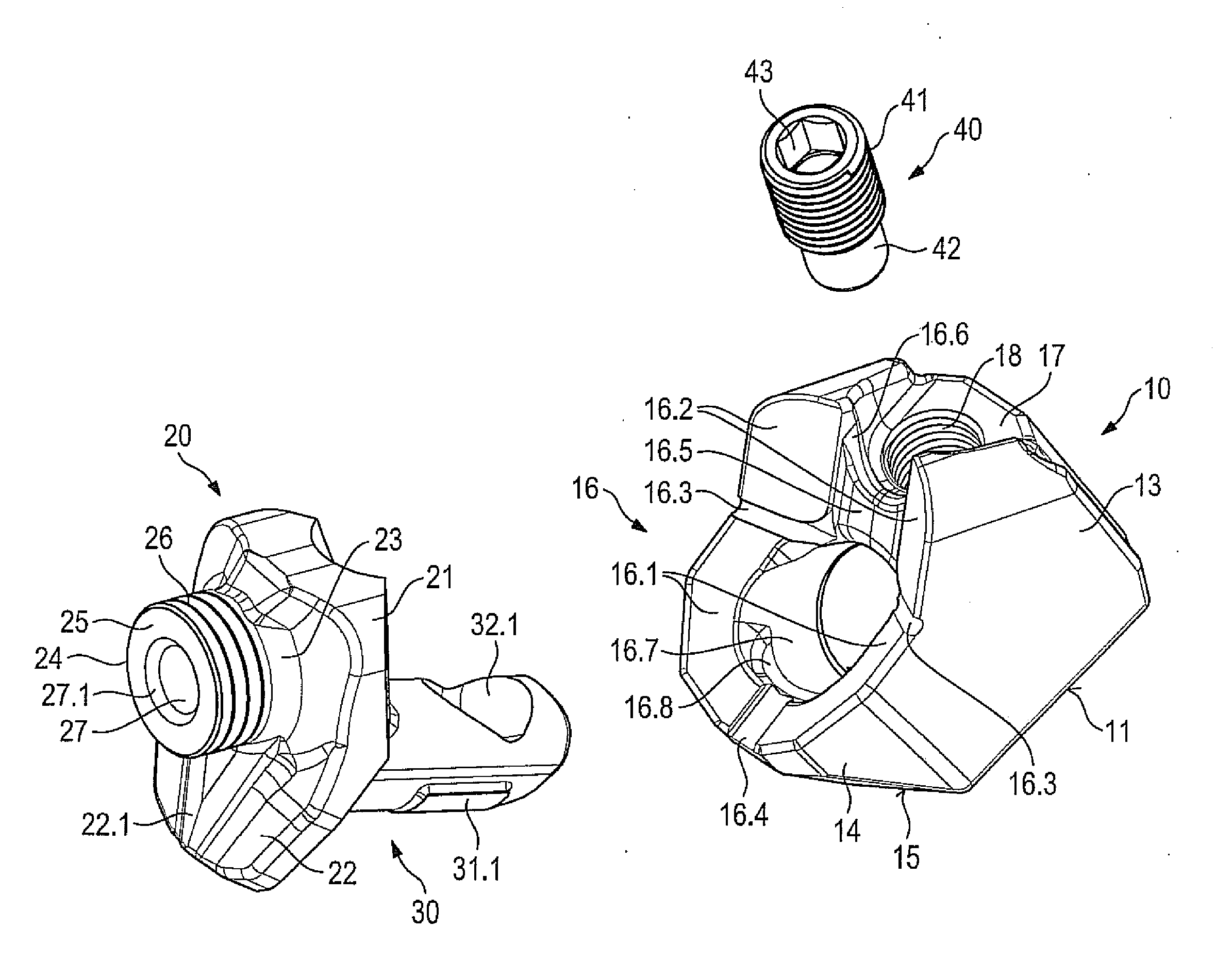
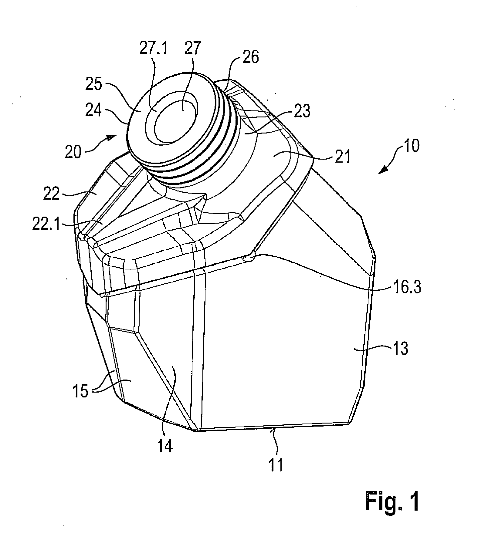
[0045]FIG. 1 shows a tool combination made up of a base part 10 and a bit holder 20. Bit holder 20 is connected replaceably to base part 10. Base part 10 comprises a solid basic member 13 that comprises a lower attachment side 11. This attachment side 11 is concavely curved, the curvature being selected in accordance with the outside diameter of a tubular milling drum. Base part 10 can thus be placed with its attachment side 11 onto the outer side of the tubular milling drum and welded in place onto it. Basic member 13 comprises on the front side a projection that is demarcated laterally by oblique surfaces 14 and at the front side by inclined surfaces 15. Inclined surfaces 15 are incident at an angle to one another, and oblique surfaces 14 adjoin inclined surfaces 15 at an angle. This results in an arrow-shaped geometry of base part 10 at the front, leading to better clearing action by base part 10.

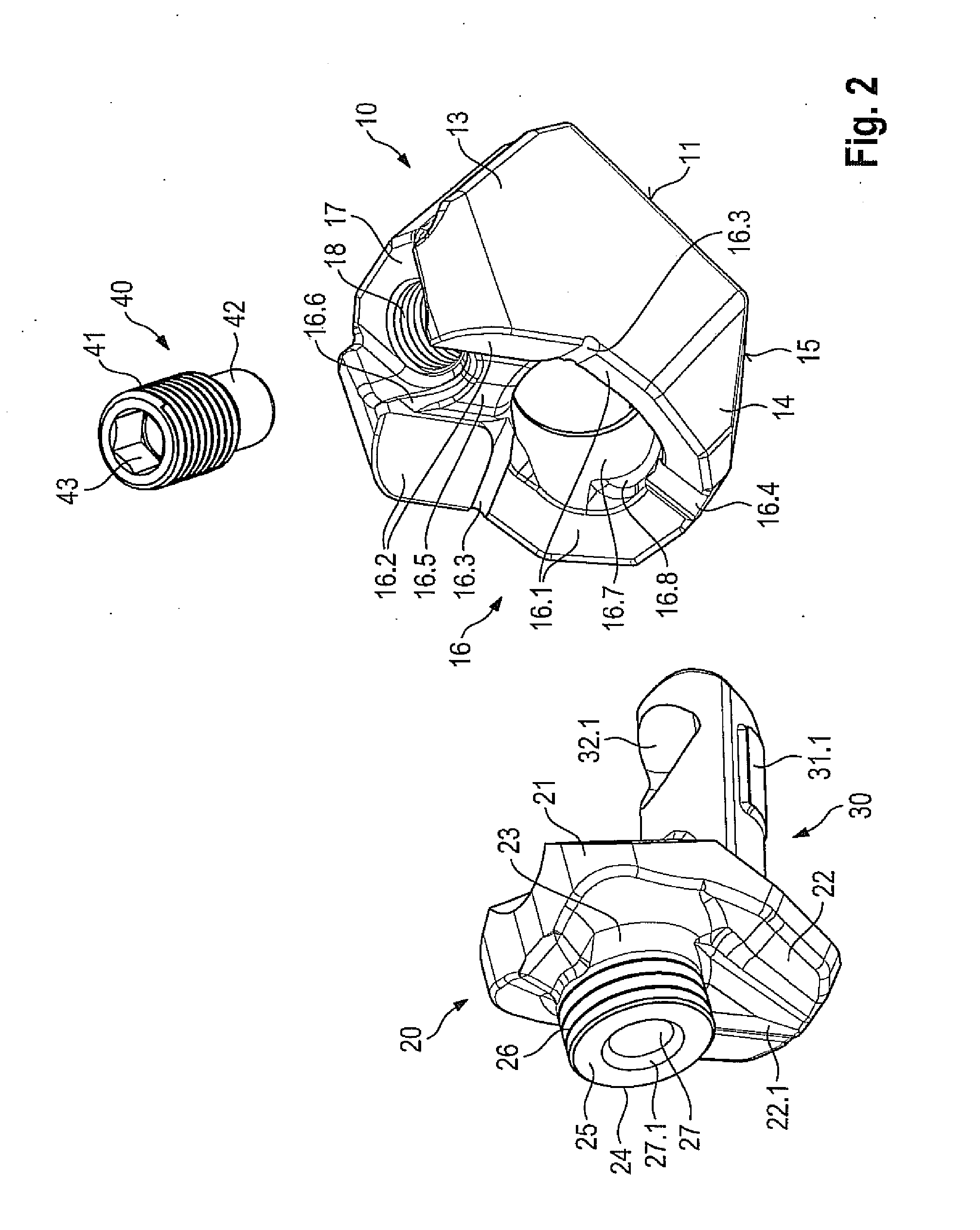
[0046]As FIG. 2 illustrates, a bit holder receptacle 16 having an insertion receptac...


PUM


Abstract

The invention relates to a bit holder for an earth working machine, in particular a road milling machine, having a support member onto which an insertion projection is indirectly or directly attached on an insertion projection side, the support member comprising two first and/or two second stripping surfaces that are at an angle to one another, and the support member having a working side that comprises a bit receptacle. In order to achieve a stable and long-lived configuration for such a bit holder, provision is made according to the present invention that the first and/or second stripping surfaces diverge from the insertion projection side toward the working side.

Description

BACKGROUND OF THE INVENTION[0001]1. Field of the Invention[0002]The invention relates to a bit holder for an earth working machine, in particular a road milling machine, a mining machine, or the like, having a support member onto which an insertion projection is indirectly or directly attached on an insertion projection side, the support member comprising two first and / or two second stripping surfaces that are at an angle to one another, and the support member having a working side that comprises a bit receptacle.[0003]2. Description of the Prior Art[0004]U.S. Pat. No. 3,992,061 discloses a bit holder that forms a support member having an integrally shaped-on insertion projection. The support member is penetrated by a cylindrical bore embodied as a bit receptacle. A working tool, in the present case a round-shank bit, can be inserted into the bit receptacle. The support member comprises two stripping surfaces, at an angle to one another, that serve for bracing against corresponding ...

Claims


Application Information

Patent Timeline
IPC IPC(8): E21C35/19
CPCE21C35/19E21C35/18E21C35/193E21B10/00E21C35/1933E21C35/191
Inventor LEHNERT, THOMASBUHR, KARSTENBARIMANI, CYRUSHAHN, GUNTERKAMMERER, KARLROTH, MARKUSDIESSNER, BERNHARD
Owner WIRTGEN GMBH
Why Eureka
Try Eureka