Quick connector

a quick connector and connector technology, applied in the direction of pipe couplings, pipes, pipes, etc., can solve the problem and achieve the effect of reducing the amount of radially inward protrusion of the pair of leg portions

Active Publication Date: 2022-07-05
SUMITOMO RIKO CO LTD
View PDF12 Cites 0 Cited by
  • Summary
  • Abstract
  • Description
  • Claims
  • Application Information

AI Technical Summary

Benefits of technology

[0006]An object of the present invention is to provide a quick connector that enables reduction of the insertion load of the first pipe.
[0007]A quick connector according to the present invention includes: a connector body into which a first pipe having an annular protrusion is to be inserted; and a retainer configured to be movable from an initial position to a confirmation position relative to the connector body through push-in operation in a direction crossing an axial direction of the connector body in a state in which the first pipe is inserted to a regular position in the axial direction of the connector body, the retainer being configured to be engaged with the annular protrusion in the axial direction at the confirmation position so as to prevent the first pipe from coming off.
[0011]According to the present invention, the expansion amount of the pair of first leg portions is smaller than that of the pair of second leg portions. That is, the pair of first leg portions are not expandable or are expandable with only a slight expansion amount. The first taper surfaces are formed, at the distal end sides of the pair of first leg portions, on the surface on the side to which the first pipe is inserted. Therefore, during a period until the first pipe is inserted to the regular position, the annular protrusion of the first pipe presses the first taper surfaces of the pair of first leg portions in the axial direction. At this time, the first taper surfaces cause the retainer to move from the initial position to the insertion position by the axial-direction pressing force from the annular protrusion of the first pipe. The retainer has a return force for returning to the initial position in a state in which the retainer is at the insertion position. Therefore, during a period until the first pipe is inserted to the regular position, the retainer moves from the initial position to the insertion position against the return force. During this period, the pair of first leg portions do not need to expand.

Problems solved by technology

In particular, since a part for provisional prevention in the retainer is provided to the pair of leg portions, the amount of radially inward protrusion of the pair of leg portions is great.

Method used


Image

  • Quick connector
  • Quick connector
  • Quick connector

Examples


Embodiment Construction

[0040](1. Outline of Quick Connector 1)

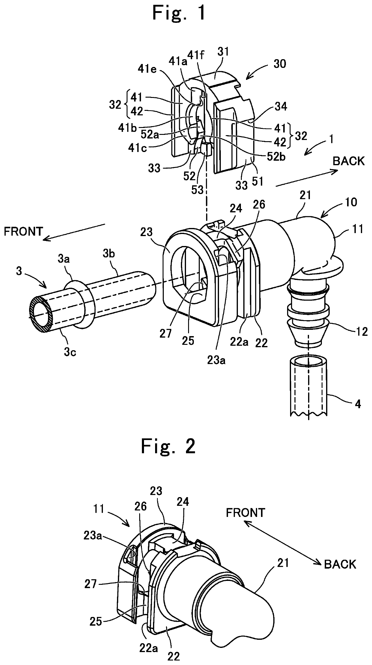
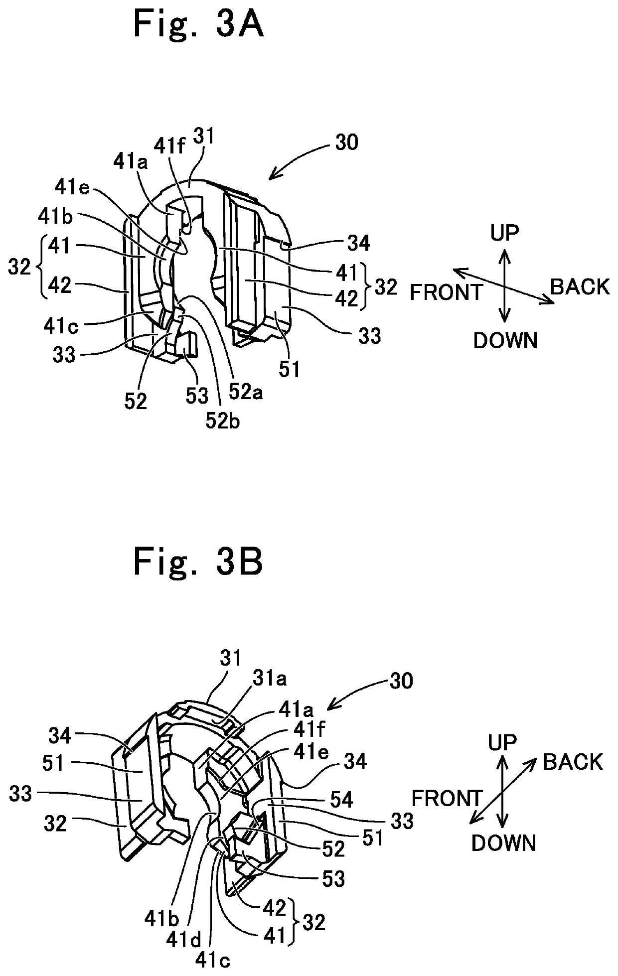
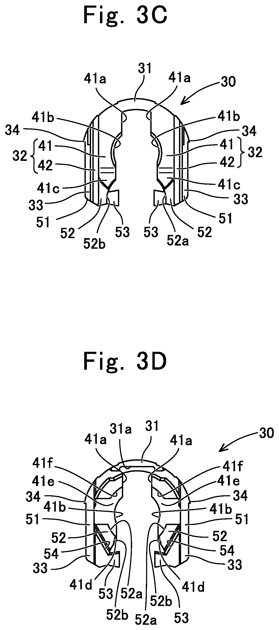
[0041]The outline of a quick connector 1 will be described with reference to FIG. 1 and FIG. 7F. The quick connector 1 forms a part of a fuel supply path of an automobile, for example. An end of a first pipe 3 is inserted to a first end side of the quick connector 1, and an end of a second pipe 4 is externally fitted to a second end side of the quick connector 1. Thus, the quick connector 1 connects the first pipe 3 and the second pipe 4.

[0042]Here, the first pipe 3 is, for example, made of metal and formed in a tubular shape, as shown in FIG. 1. The first pipe 3 has an annular protrusion 3a (also called flange or bead) formed so as to protrude outward in the radial direction at a position distant in the axial direction from the endmost point by a predetermined distance, an end tube portion 3b which is a small-diameter part on the end side with respect to the annular protrusion 3a, and a non-end tube portion 3c which is a small-diameter part on...


PUM


Abstract

A pair of first leg portions of a retainer have first taper surfaces at distal end sides on surfaces on the side to which a first pipe is to be inserted. The first taper surfaces cause the retainer to move from an initial position to an insertion position by an axial-direction pressing force from an annular protrusion, during a period until the first pipe is inserted to a regular position. During the period until the first pipe is inserted to the regular position, a pair of second leg portions restrict the retainer from moving from the initial position to a confirmation position. In a state in which the first pipe is inserted to the regular position, the pair of second leg portions allow the retainer to move from the initial position to the confirmation position.

Description

CROSS REFERENCE TO RELATED APPLICATIONS[0001]The present application is a Continuation Application of International Application No. PCT / JP2019 / 014427, filed on Apr. 1, 2019, which is incorporated herein by reference. The present invention is based on Japanese Patent Application No. 2018-084830, filed on Apr. 26, 2018, the entire contents of which are incorporated herein by reference.BACKGROUND OF THE INVENTION1. Field of the Invention[0002]The present invention relates to a quick connector.2. Description of the Related Art[0003]JP6149081B2, JP5753284B1, and JP2015-48917A disclose quick connectors that allow confirmation that a first pipe (metal pipe) made of metal has been inserted to a regular position, by a retainer, and fully prevent the first pipe from coming off, by the retainer. Further, in a state in which the first pipe is inserted to the regular position and the retainer is at an initial position before moving to a confirmation position, the retainer provisionally prevents ...

Claims


Application Information

Patent Timeline
Patent Type & Authority Patents(United States)
IPC IPC(8): F16L37/14
CPCF16L37/14F16L37/144F16L2201/10
Inventor KANEGAE, RYOUSUKESAKAZAKI, KAZUSHIGEITO, MAKOTO
Owner SUMITOMO RIKO CO LTD
Why Eureka
Try Eureka