Charge connector

a technology of charging connectors and connectors, applied in the direction of charging stations, transportation and packaging, coupling device connections, etc., can solve the problems of complicated operation of assembling the charging connectors, and achieve the effect of improving the operability of assembly of the charging connectors

Active Publication Date: 2017-03-21
YAZAKI CORP
View PDF15 Cites 7 Cited by
  • Summary
  • Abstract
  • Description
  • Claims
  • Application Information

AI Technical Summary

Benefits of technology

[0016]The present invention has been made in order to solve the above-mentioned problem. An object of the present invention is to provide a charge connector capable of reliably holding a connector housing at a temporarily housed position in one case split member so as to improve operability of assembly of the charge connector.
[0020]According to the aspects of the present invention, since the temporarily holding portion is locked at the temporarily held portion in a state where the connector housing is located at the temporarily housed position in the one case split member, an operator can keep the connector housing at the temporarily housed position in the one case split member so as to improve the operability of assembly of the charge connector.

Problems solved by technology

However, the conventional charge connector 100 described above has a problem that the engagement between the rotation direction regulation holes 114B and the rotation direction regulation projections 123 is released because the connector housing 121 located at the temporarily housed position in the one case split member 110A rises up from the one case split member 110A due to external force such as tensile force of the electric wires W. As a result, the operator is required to hold and keep the connector housing 121 at the temporarily housed position in the one case split member 110A to assemble the charge connector 100, which complicates the operation of assembling the charge connector 100.

Method used


Image

  • Charge connector
  • Charge connector
  • Charge connector

Examples


Embodiment Construction

[0030]Hereinafter, a charge connector according to the present invention will be described below with reference to the drawings. Here, the same or similar elements in the following descriptions of the drawings are indicated by the same or similar reference numerals. It should be noted that the respective elements are schematically shown in the drawings, and dimensional ratios in the drawings are different from actual ratios. The specific dimensions thus should be taken into consideration in accordance with the following descriptions. In addition, the respective drawings may include the elements which are equivalent but differ in dimensional ratio.

(Configuration of Charge Connector)

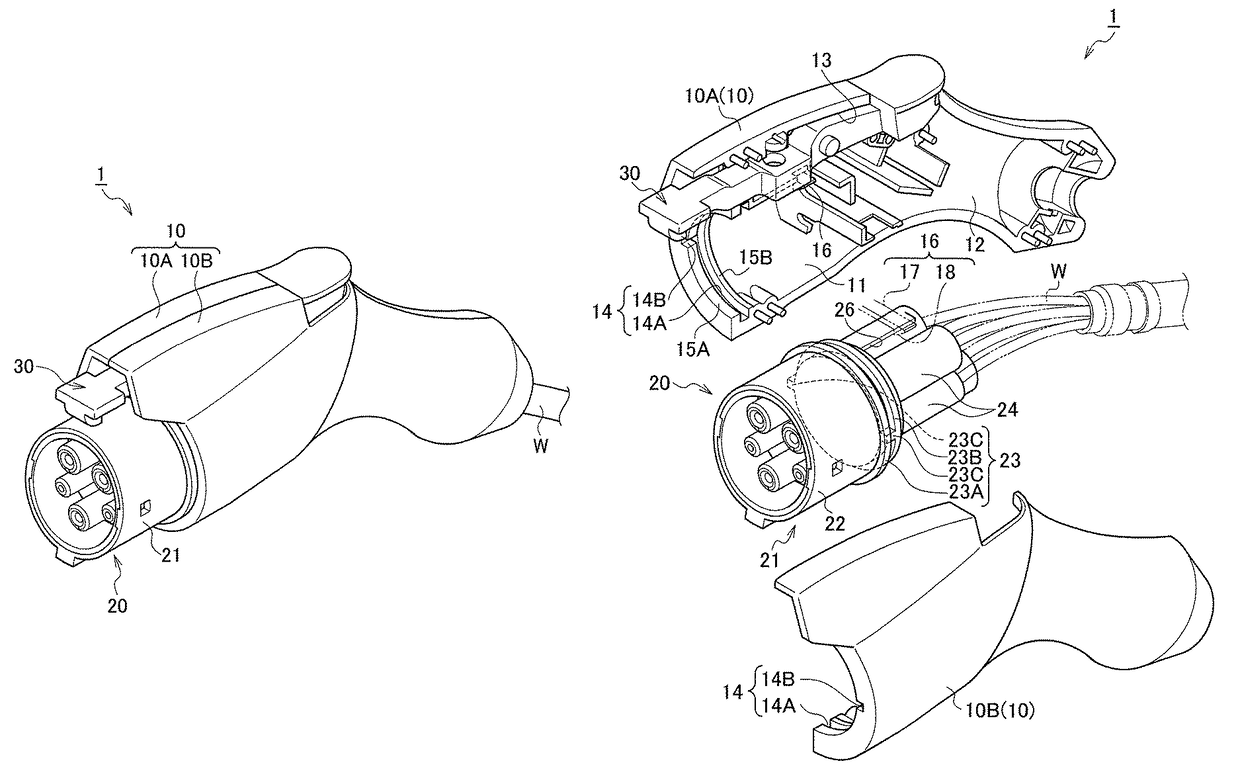
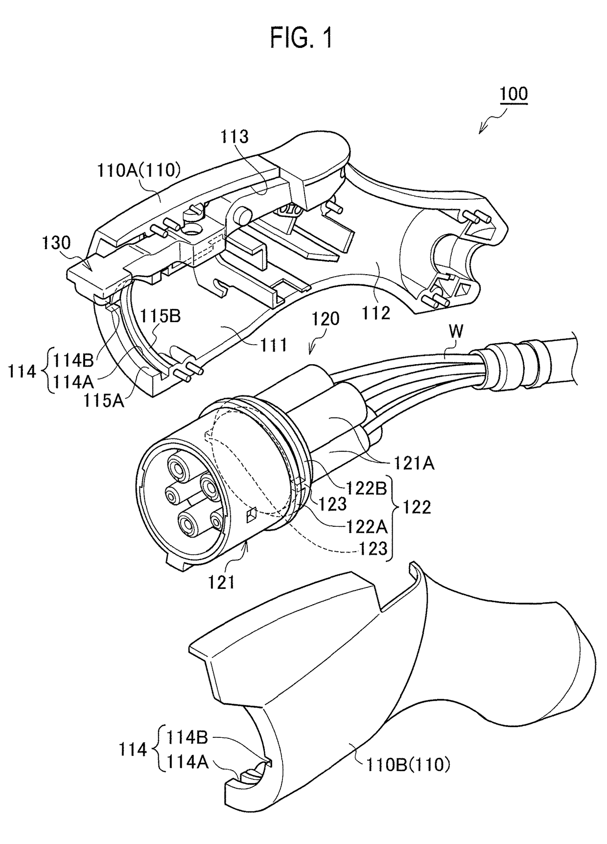
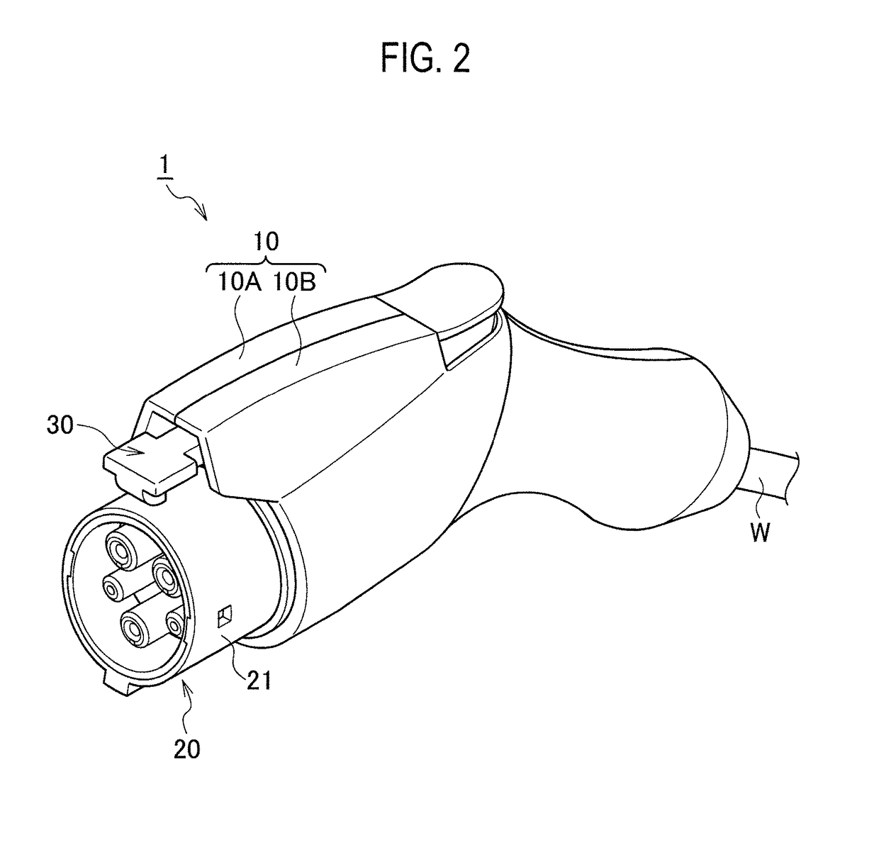
[0031]First, a configuration of a charge connector 1 according to the present embodiment will be described below with reference to the drawings. FIG. 2 is a perspective view showing the charge connector according to the present embodiment. FIG. 3 and FIG. 4 are exploded perspective views each showing the c...


PUM


Abstract

A charge connector includes a connector case and a connector body. The connector case includes a pair of case split members to be coupled together. The connector body is housed in the connector case and includes charge terminals connected with electric wires and housed in a connector housing. The connector housing is provided with rotation direction regulation projections. The case split members are provided with rotation direction regulation holes that engage with the rotation direction regulation projections. The case split member is provided with a temporarily holding portion for holding the connector housing at a temporarily housed position. The connector housing is provided with a temporarily held portion at which the temporarily holding portion is locked.

Description

CROSS REFERENCE TO RELATED APPLICATION[0001]This is a continuation application based on PCT application No. PCT / JP2013 / 077090 filed on Oct. 4, 2013, which claims the benefit of priority from Japanese Patent Application No. 2012-222936 filed on Oct. 5, 2012, the entire contents of which are incorporated by reference herein.BACKGROUND OF THE INVENTION[0002]1. Field of the Invention[0003]The present invention relates to a charge connector used for charging a battery mounted on a vehicle such as an electric vehicle and a hybrid electric vehicle.[0004]2. Description of the Related Art[0005]Conventionally, a charge connector is used for charging a battery mounted on a vehicle such as an electric vehicle (EV) and a hybrid electric vehicle (HEV) (refer to Japanese Unexamined Patent Application Publication No. 2010-182471). An example of such a charge connector will be described below with reference to FIG. 1.[0006]A conventional charge connector 100 shown in FIG. 1 includes a connector case...

Claims


Application Information

Patent Timeline
Patent Type & Authority Patents(United States)
IPC IPC(8): H01R13/62H01R13/516H01R13/506H01R13/639B60L11/18
CPCH01R13/506B60L11/1816H01R13/516B60L11/1818H01R13/639H01R13/46H01R43/00H01R43/20B60L53/16Y02T10/70Y02T10/7072Y02T90/14
Inventor FUKUSHIMA, HIROTAKAOKUDA, SATOSHISAWADA, TSUTOMU
Owner YAZAKI CORP
Why Eureka
Try Eureka