
Electrode arrangement for an electrodynamic fragmentation plant

a technology of electrodynamic fragmentation and electrodynamics, applied in grain treatment and other directions, can solve the problems of high operation cost, corresponding change in the target size of readily fragmented materials, and relative cost of electrodynamics in manufacturing, and achieve the effect of negative effect on fragmentation performan

Active Publication Date: 2017-03-28
SELFRAG
View PDF19 Cites 1 Cited by
  • Summary
  • Abstract
  • Description
  • Claims
  • Application Information

AI Technical Summary

Benefits of technology

The invention is an electrode arrangement that allows for economical and efficient fragmentation of material using small high-voltage pulses. This arrangement can expand the target value range of existing plants by retrofitting them. The charging and transportation of the material can be done without additional equipment, as gravity is used.

Problems solved by technology

An important disadvantage of the construction principals disclosed in DE 195 34 232 A1 and GB 2 342 304 comprising bottom electrodes or wall electrodes, respectively, which are designed as a sieve, consists in that these electrodes are relative costly in manufacturing, which in the light of the fact that the electrodes in electrodynamic fragmentation processes are comsumables, leads to high costs of operation.
Further, there is the disadvantage, that the size of the sieve openings increases during operation, which leads to a corresponding change in the target size of the readily fragmented material.
All of the before mentioned arrangements furthermore have the disadvantage that the distance between the electrodes are equal to or bigger than the sieve openings or discharge openings, respectively, which in case that a coarse fragmentation is desired leads to relative large electrode distances with the requirement of providing high-voltage pulses of corresponding magnitude.
This in turn requires the use of very expensive high-voltage pulse generators.

Method used


Image

  • Electrode arrangement for an electrodynamic fragmentation plant
  • Electrode arrangement for an electrodynamic fragmentation plant
  • Electrode arrangement for an electrodynamic fragmentation plant

Examples


Embodiment Construction

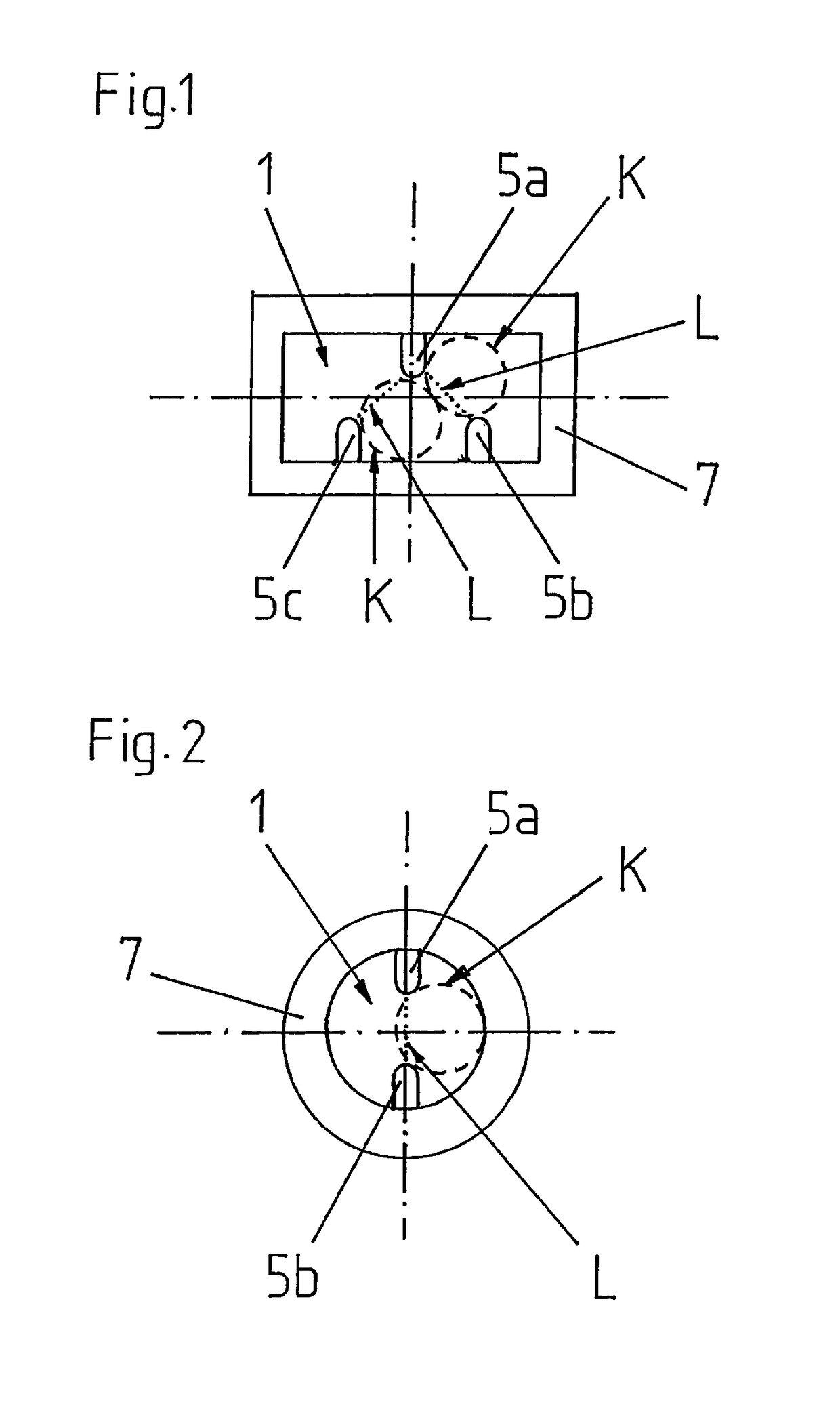
[0081]FIG. 1 shows a first electrode arrangement according to the invention for an electrodynamic fragmentation plant in a topview. As can be seen, the electrode arrangement comprises a passage opening 1 having a rectangular basic shape or cross-sectional shape, respectively, for fragmentation material, from the outer boundaries of which three stick-shaped electrode protrusions 5a, 5b, 5c protrude into the passage opening, thereby leaving open the center of the passage opening 1.

[0082]The outer boundaries of the passage opening 1 are formed by an isolator body 7. The electrode protrusions 5a, 5b, 5c are formed by single-electrodes, which are carried by the isolator body 7.

[0083]The two electrodes 5b, 5c which are commonly arranged at one side of the outer boundaries of the passage opening 1 are via a line (not visible) in an electrically conductive manner connected with each other and via the isolator body 7 are electrically isolated with respect to the electrode 5a, which is arrang...


PUM


Abstract

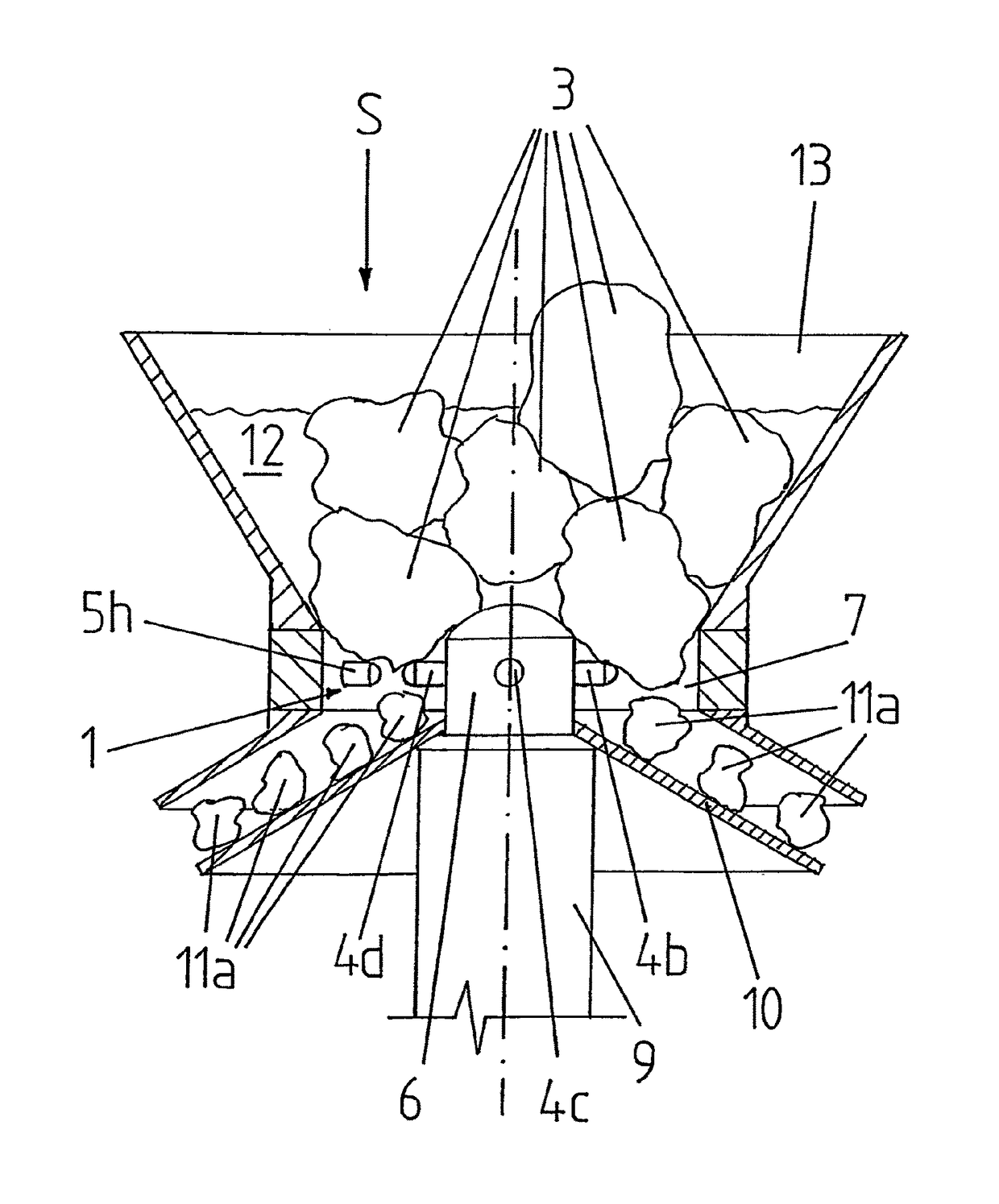
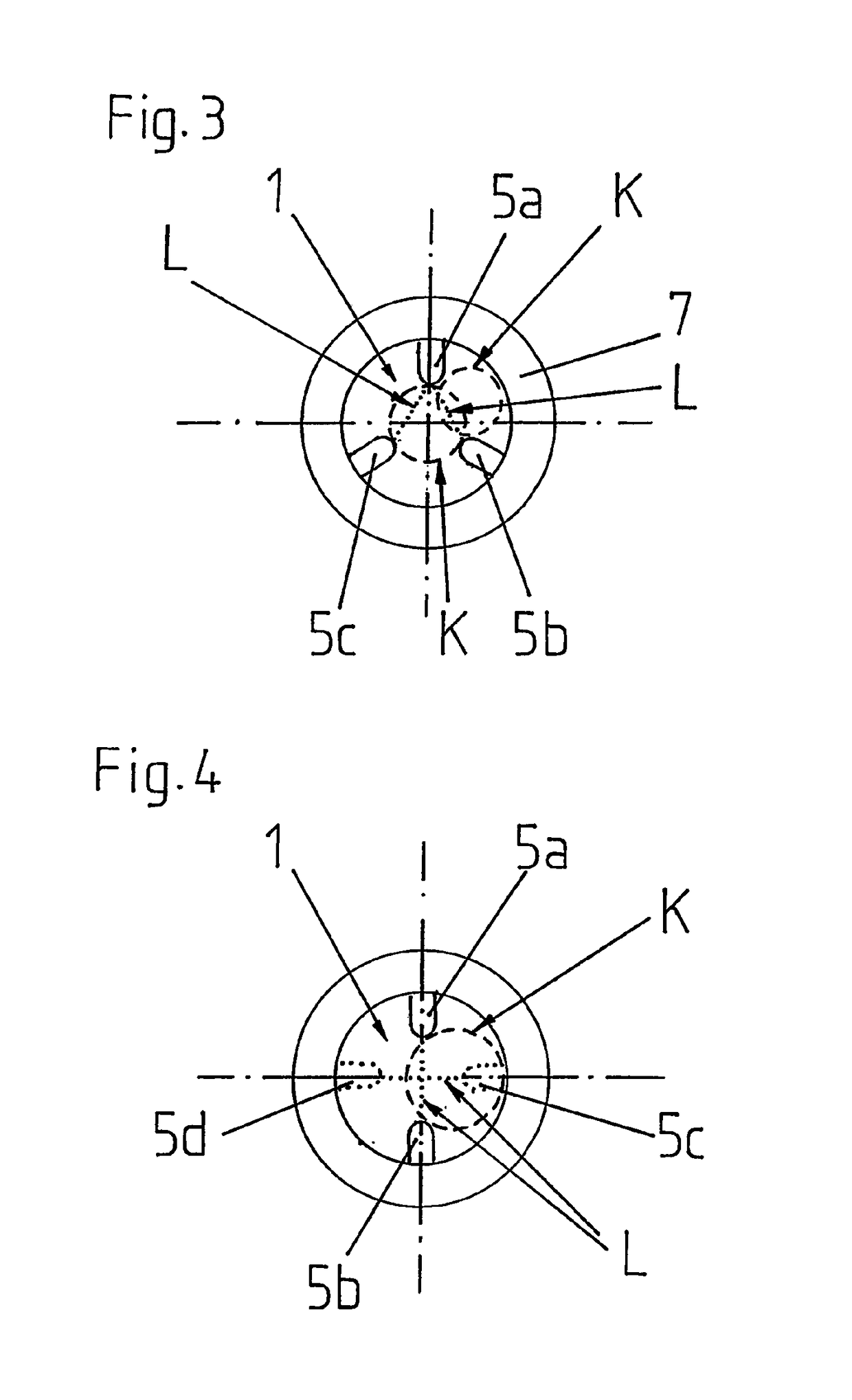
The invention relates to an electrode arrangement for an electrodynamic fragmentation plant having a passage opening (1) for fragmentation material (3) and having several electrode pairs (4a, 5a; 4a, 5b; 4b, 5c; 4b, 5d; 4c, 5e; 4c, 5f; 4d, 5g; 4d, 5h) by means of which, by charging the electrodes (4a-4d, 5a-5h) thereof with high-voltage pulses, in each case high-voltage discharges can be generated within the passage opening (1), for fragmentation of the fragmentation material (3). The passage opening (1) is formed in such a way and the electrodes (4a-4d, 5a-5h) of the electrode pairs are arranged therein in such a way that for each electrode pair (4a, 5a; 4a, 5b; 4b, 5c; 4b, 5d; 4c, 5e; 4c, 5f; 4d, 5g; 4d, 5h) in the area of a shortest connecting line (L) between the electrodes of the respective electrode pair, a ball (K) can pass through the passage opening (1), the diameter of which is bigger than the length of this respective shortest connecting line (L).With such an electrode arrangement it is possible to carry out an electrodynamic fragmentation of fragmentation material in an economical manner with comparatively small high-voltage pulses. This also results in the possibility of expanding the realizable target value range of existing plants considerably in the direction of larger target values by retrofitting such plants with the electrode arrangement according to the invention.

Description

TECHNICAL FIELD[0001]The invention relates to an electrode arrangement for an electrodynamic fragmentation plant, to a fragmentation plant comprising such an electrode arrangement as well as to a method for fragmenting material pieces using such an electrode arrangement according to the preambles of the independent claims.PRIOR ART[0002]In the electrodynamic fragmentation, the fragmentation material, for example a bulk of concrete pieces, is arranged between two electrodes and by charging the electrodes with high-voltage pulses, which lead to high-voltage breakdowns through the fragmentation material, is fragmented.[0003]In case the fragmentation material shall be fragmented to a specific target size, it is withdrawn from the fragmentation zone once it has reached the target size.[0004]For doing so, the fragmentation zone is designed in such a way that it boundaries feature one or several openings having a size corresponding to the target size, through which the fragmentation materi...

Claims


Application Information

Patent Timeline
Patent Type & Authority Patents(United States)
IPC IPC(8): B02C19/18
CPCB02C19/18B02C2019/183
Inventor MULLER-SIEBERT, REINHARDMONTI DI SOPRA, FABRICEHASLER, BERNHARDGIESE, HARALD
Owner SELFRAG
Learn More