
Passive exhaust valve with floating spring stop

a technology of spring stop and exhaust valve, which is applied in the direction of valve housing, machine/engine, electric control of exhaust treatment, etc., can solve the problems of pre-mature wear and damage of the valve, other negative consequences of the exhaust system performance, and the assembly of the passive exhaust valve can also create other noises, so as to reduce the closure speed of the valve plate, reduce or substantially eliminate the noise of the closure and the associated impact force

Active Publication Date: 2017-03-28
MIDDLEVILLE ENGINEERED SOLUTIONS LLC
View PDF38 Cites 12 Cited by
  • Summary
  • Abstract
  • Description
  • Claims
  • Application Information

AI Technical Summary

Benefits of technology

The present invention provides an exhaust conduit with a valve plate that can regulate the flow of exhaust gases. The valve has a flexible bumper element that reduces closure noises and impact forces. The bumper element can be partially or fully positioned out of the flow path and biased inward to gradually close the valve. The bumper element can also be floating or movably engaged with the exhaust conduit. This invention helps to improve the performance and comfort of exhaust systems.

Problems solved by technology

Passive valves may regulate exhaust pressure and attenuate exhaust system noise, however, passive exhaust valve assemblies can also create other noises, such as, for example, harsh closure noises of a valve plate closing against an interior surface of a valve conduit, flutter noises of the valve plate flapping or fluttering between open and closed positions when experiencing exhaust pressure fluctuations or pulses, and squeaking noises of the valve plate pivoting between open and closed positions.
As generally understood, these undesirable noises may also cause pre-mature wear and damage to the valve and other negative consequences to performance of the exhaust system.

Method used


Image

  • Passive exhaust valve with floating spring stop
  • Passive exhaust valve with floating spring stop
  • Passive exhaust valve with floating spring stop

Examples


Embodiment Construction

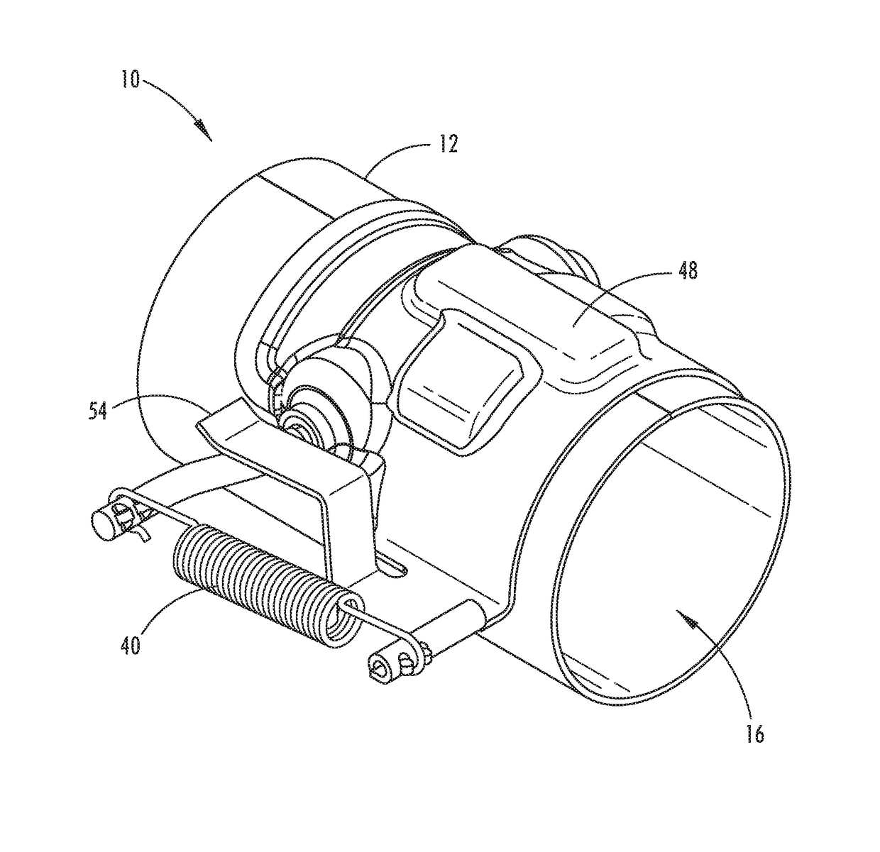
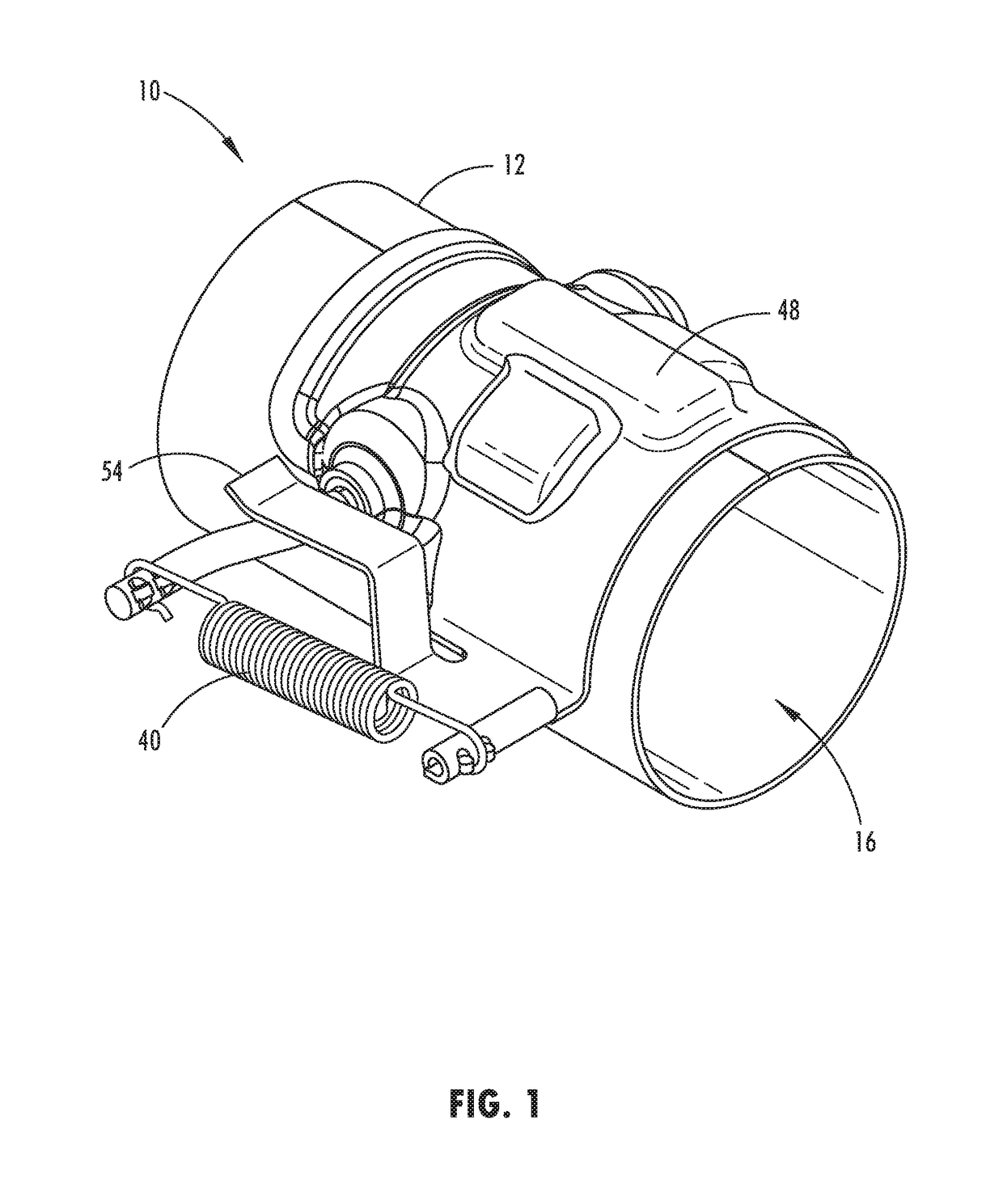
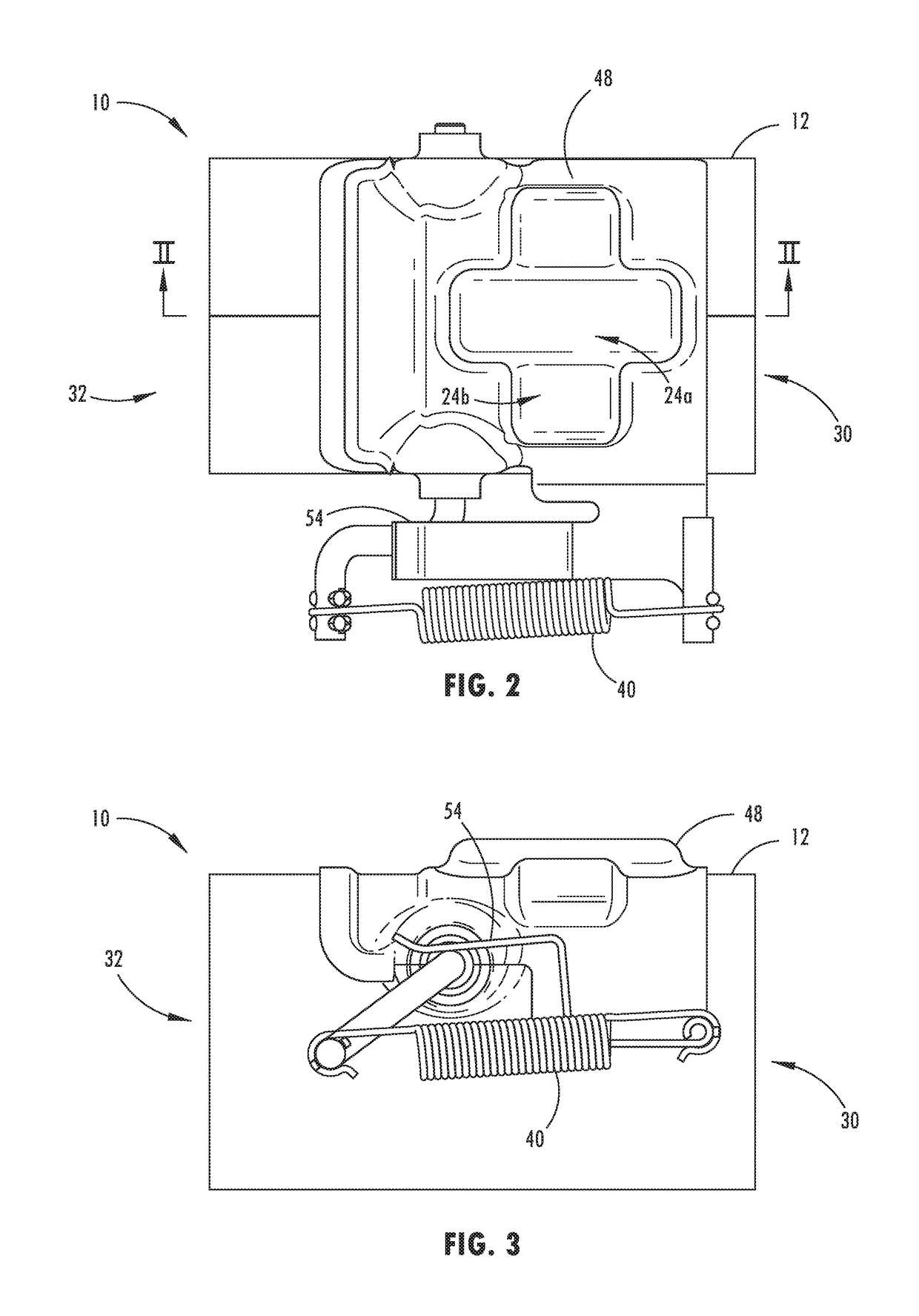
[0029]Referring now to the drawings and the illustrative embodiments depicted therein, a passive exhaust valve assembly 10 includes an exhaust conduit 12, such as tube or pipe, and a vane member or valve plate 14 (FIG. 4) that pivots within an interior section 16 or volume of the exhaust conduit 12 between a closed position 20 (FIG. 5) and an open position 18 (FIG. 12) to regulate the flow of exhaust gases through the exhaust conduit 12. The valve plate 14 is biased to the closed position 20 and pivots toward the open position 18 when the flow of exhaust gas generates enough pressure to overcome the biasing force about a pivotal axis of the valve plate 14, such as the biasing force provided by spring 40 shown in FIG. 1. A flexible bumper element, such as a metal mesh pad 22, is disposed at or on an interior surface 26 of the exhaust conduit 12 in a location to contact the valve plate 14 moving toward the closed position 20. For example, as shown in FIG. 5, the bumper element 22 may ...


PUM


Abstract

A passive exhaust valve assembly includes an exhaust conduit or pipe section with a valve plate or vane member that can pivot within the interior section or volume of the exhaust conduit to regulate the flow of exhaust gases through the exhaust conduit. A flexible bumper element, such as a metal mesh pad, may be positioned on the interior surface of the exhaust conduit, such that an end portion of the valve plate may contact the mesh pad in the closed position. The bumper element may be disposed in a recessed pocket or depression and may be biased inward, such as with a spring, for the end portion of the valve plate to contact the bumper element as it moves toward the closed position, and thereby gradually reduce the closure speed of the valve plate to the closed position.

Description

CROSS-REFERENCE TO RELATED APPLICATIONS[0001]The present application claims benefit under 35 U.S.C. §119(e) of U.S. Provisional Application Ser. No. 62 / 387,411, entitled PASSIVE EXHAUST VALVE WITH FLOATING SPRING STOP, filed Dec. 24, 2015, which is hereby incorporated herein by reference in its entirety.FIELD OF THE INVENTION[0002]The present invention relates generally to the field of passive exhaust valves and methods of forming and assembling such valves.BACKGROUND OF THE INVENTION[0003]To control back flow pressure and reduce low frequency engine noise in exhaust systems of combustion engines, it is generally understood that a passive valve may be provided in the exhaust line to alter characteristics of exhaust flow by actuating in response to changes in exhaust pressure. Passive valves may regulate exhaust pressure and attenuate exhaust system noise, however, passive exhaust valve assemblies can also create other noises, such as, for example, harsh closure noises of a valve pla...

Claims


Application Information

Patent Timeline
IPC IPC(8): F16K15/03F16K47/04F16K25/00F01N13/08F16K27/02
CPCF01N13/08F16K25/00F16K47/04F16K15/033F16K27/0209F01N9/00F01N2240/36F01N2900/1406F02D9/04Y02T10/40
Inventor MIDDLETON, JR., ROBERT LEROYMIDDLETON, JUSTIN TYLERMIDDLETON, SR., ROBERT LEROY
Owner MIDDLEVILLE ENGINEERED SOLUTIONS LLC
Learn More