Smart entry system

a technology of smart entry and vehicle, applied in the field of vehicle smart entry system, can solve the problem of low possibility of mobile device staying within the second transmission area for a predetermined time, and achieve the effect of enhancing user convenien

Active Publication Date: 2017-03-28
HONDA MOTOR CO LTD
View PDF24 Cites 5 Cited by
  • Summary
  • Abstract
  • Description
  • Claims
  • Application Information

AI Technical Summary

Benefits of technology

[0008]According to the first aspect, even after a first transmission area has been narrowed to a second transmission area, it is detected periodically or with a second cyclic period whether or not the mobile device is present within the first transmission area which is not narrowed (hereinafter also referred to as “unnarrowed first transmission area”). If it has been determined that the mobile device is not present within the unnarrowed first transmission area after the narrowing of the first transmission area to the second transmission area, it means that the mobile device has got away (i.e., has been moved away) from the vehicle out of the first transmission area after staying within the first transmission area for a predetermined time or over. In such a situation, the first transmission area need not be narrowed to the second transmission area any longer. Thus, upon determination that the mobile device has entered the reset (set-again) first transmission area, the smart entry system of the invention can unlock doors of the vehicle, for example. Also, upon determination that the mobile device has entered the reset (set-gain) first transmission area, the smart entry system can turn on a light emitting section, such as blinkers or direction indicators, of the vehicle, for example. Therefore, for using the smart entry system, a user need not approach the vehicle until the user enters the second transmission area narrowed from the first transmitter area, and thus, user convenience is enhanced.
[0012]In the fifth aspect depending on any one of the first to fourth aspects, the smart entry system further comprises a notification section that provides a user with notification information corresponding to the second transmitter power output lowered from the first transmitter power output. According to the fifth aspect, the notification section can provide the user with notification information corresponding to the second transmitter power output, i.e. can inform the user that the first transmission area has been narrowed to the second transmission area after the mobile device was placed within the first transmission area. Particularly, after it is determined that the mobile device has entered the second transmission area narrowed from the first transmission area, the notification section may provide the notification information corresponding to the second transmitter power output. For example, because the notification information is provided to the user next time the user gets in the vehicle, the user can recognize more reliably that the first transmission area has been narrowed to the second transmission area.
[0017]In eighth aspect depending on the seventh aspect, the smart entry system further comprises a notification section that provides a user with notification information corresponding to the first transmitter power output. According to the eighth aspect, the notification section can provide the user with notification information corresponding to the first transmitter power output, i.e. can inform the user of the first transmission area having been set in accordance with a position of the vehicle. Therefore, the user can readily recognize how far away from the vehicle the mobile device should be located.

Problems solved by technology

Further, because the second transmission area, rather than the first transmission area, is set as the user gets off the vehicle, there is a low possibility of the mobile device continuing to stay within the second transmission area for a predetermined time or over.

Method used


Image

  • Smart entry system
  • Smart entry system
  • Smart entry system

Examples


Embodiment Construction

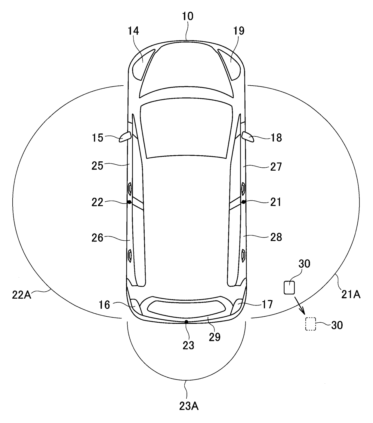
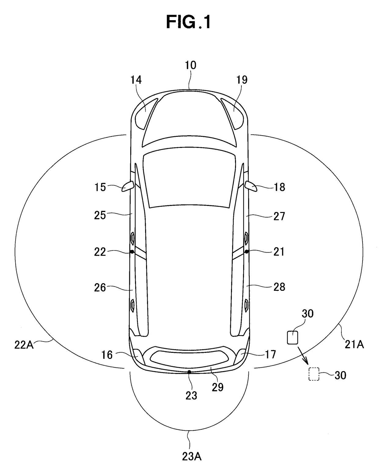
[0026]The following will describe the preferred embodiments, but it should be appreciated that the present invention is not limited to the described embodiments and various modifications of the embodiments are possible without departing from the basic principles. The scope of the present invention is therefore to be determined solely by the appended claims. FIG. 1 is a view explanatory of an exemplary transmission area of a smart entry system according to the present invention. As shown in FIG. 1, such a transmission area is set outside of a vehicle 10 that is, for example, a motor vehicle. The transmission area shown in FIG. 1 is a first transmission area (hereinafter sometimes referred to as “first overall transmission area”) that is set first as a user or passenger gets off the vehicle 10. The first transmission area (first overall transmission area) comprises, for example, three first transmission area portions or sub-areas 21A, 22A and 23A. In FIG. 1, a mobile device 30 depicte...


PUM


Abstract

A smart entry system comprises a communication section and a control device. Upon determination that a mobile device has continued to be present within a first transmission area for a predetermined time or over, the control device lowers first transmitter power output of a first electromagnetic wave to be transmitted from the communication section to second transmitter power output of the first electromagnetic wave so that the first transmission area is narrowed to a second transmission area until no more response is received from the mobile device. Then, the communication section not only transmits the first electromagnetic wave having the second transmitter power output and generating the second transmission area but also transmits, with a second cyclic period longer than the first cyclic period, a second electromagnetic wave, the second electromagnetic wave has the first transmitter power output and generates the first transmission area which is not narrowed.

Description

CROSS-REFERENCE TO RELATED APPLICATION[0001]This application claims priority to and the full benefit of Japanese Patent Application No. 2013-174338 filed Aug. 26, 2013 and incorporates the Japanese application by reference herein in its entirety.FIELD OF THE INVENTION[0002]The present invention relates generally to an improvement of smart entry systems for vehicles.BACKGROUND OF THE INVENTION[0003]Japanese Patent Application Laid-open Publication No. 2008-14095 (hereinafter referred to as “the relevant patent literature”) discloses a vehicular keyless apparatus including a mobile device and a vehicle-mounted device. The vehicle-mounted device includes a control section as a control device, and the control section is connected to a communication section having, for example, an LF (Low Frequency) transmission section, a vehicular external antenna output section and antennas. Further, according to the disclosure of the relevant patent literature, once it is determined that the mobile d...

Claims


Application Information

Patent Timeline
Patent Type & Authority Patents(United States)
IPC IPC(8): G07C9/00
CPCG07C9/00309G07C2009/00333G07C2009/00793G07C2209/63Y02B60/50
Inventor YAMANE, KATSUYASUYAMAZAKI, MASAYUKI
Owner HONDA MOTOR CO LTD
Why Eureka
Try Eureka